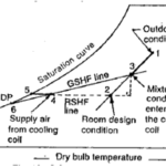
The air quantity required offsetting simultaneously the room sensible and latent loads and the air quantity required through the apparatus to handle the total sensible and latent loads may be calculated, using the conditions on their respective RSHF and GSHF lines. For a particular application, when both the RSHF and GSHF ratio lines are plotted on the psychrometric chart, the intersection of the two lines represents the condition of the supply air to the space. It is also the condition of the air leaving the apparatus. The figure below illustrates what actually happens when these supplementary loads are considered in plotting the RSHF and GSHF lines.

RSHF and GSHF Line Plotted with Supplementary Load Line
Point (1) is the condition of air leaving the apparatus and point (2) is the condition of supply air to the space. Line (1 – 2) represents the temperature rise of the air stream resulting from fan horsepower and heat gain into duct. Point (3) is the room design condition and point (4) is the mixture conditions entering the cooling coil (result of mixing return air and outside air).
The air quantity (mass flow rate) required to satisfy the room load may be calculated from the following equation:
RSH = m * Cp * ∆T
In volumetric terms air flow rate in cubic feet per minute (CFM) is estimated below:
For air at ρ = 0.075 lbm/ft3 and Cp = 0.24
RSH = 0.075 * 0.24 * CFM x ∆T / 60
RSH = 1.08 x CFM x (T 3 – T 2)
CFM = RSH / [1.08 x (T 3 – T 2)]
The air quantity required through the air conditioning apparatus, to satisfy the total air conditioning load (including the supplementary loads) may be calculated from the following equation:
GSH = 1.08 x CFM x (T 4 – T 1)
CFM = GSH / [1.08 x (T 4 – T 1)]
For all practical purposes, the required air quantity supplied to the space is equal to the air quantity required through the apparatus, neglecting leakage losses.
In well designed, tight systems the difference in supply air temperature and the condition of the air leaving the apparatus (T2 – T1) is usually no more than a few degrees. The difference in temperature between the room and the air supply to the room determines the amount of air required to satisfy the room sensible and latent loads. As this temperature difference increases (supplying colder air, since the room conditions are fixed), the required air quantity to the space decreases. This temperature difference can increase up to a limit where the RSHF line crosses the saturation line on the psychrometric chart; if it is assumed that the available conditioning equipment is able to take the air to 100% saturation.
The value of T 4 is determined by hit and trial. When the supply, return, and outdoor air temperatures are known equation below can be used to calculate outside air percentage or the mixed air temperature.

This equation assumes that perfect mixing occurs; the temperature or moisture content of the mixed air stream will be the same regardless of where they are measured in the air stream. This approach works best when there are significant differences between the outdoor air temperature and the return temperature.
Once the required air flow rate (CFM) is known, the room specific humidity differential (∆w in lb of water vapor per lb of dry air) can be estimated as:

Where
∆ w = Specific humidity differential in lbw/lba
RLH = Room latent heat, Btu/hr
CFM = calculated air flow rate
ρ = air density (0.075 lb/ft3 at 60ºF)
hw = latent heat of vaporization (1059 Btu/lb, at 60ºF)
60 = min/hr
Example
Consider an interior core room of a building has a sensible load of 120000 Btu/h; a latent load of 30000 Btu/h and is conditioned by a single zone AHU. The inside conditions to be maintained are 78°F dry bulb and 50% RH and the design supply air temperature is 58°F. Determine the air flow requirements.
The design airflow rate (CFM) will be:
CFM = RSH / [1.08 x (T Room – T Supply Air)]
Air flow rate (CFM) = 120,000 / [1.08 x (78 – 58)]
Air flow rate (CFM) = 5555 CFM
The point defined by these two differential values can be plotted on a psychrometric chart. The validity of the point must be verified, based on the cooling capabilities of the coil, and the AHU arrangements.