Quick return mechanisms are used in machine tools such as shapers and power driven saws for the purpose of giving the reciprocating cutting tool a slow cutting stroke and a quick return stroke with a constant angular velocity of the driving crank.
Whitworth quick return motion mechanism–Inversion of slider crank mechanism.
This mechanism is mostly used in shaping and slotting machines. In this mechanism, the link CD (link 2) forming the turning pair is fixed, as shown in Fig. The link 2 corresponds to a crank in a reciprocating steam engine. The driving crank CA (link 3) rotates at a uniform angular speed. The slider (link 4) attached to the crank pin at A slides along the slotted bar PA (link 1) which oscillates at a pivoted point D. The connecting rod PR carries the ram at R to which a cutting tool is fixed. The motion of the tool isconstrained along the line RDproduced, i.e. along a line passing through D and perpendicular to CD.

Fig.1.29
When the driving crank CA moves from the position CA1 to CA2 (or the link DP from the position DP1 to DP2) through an angle α in the clockwise direction, the tool moves from the left hand end of its stroke to the right hand end through a distance 2 PD.
Now when the driving crank moves from the position CA2 to CA1 (or the link DP from DP2 to DP1 ) through an angleβ in the clockwise direction, the tool moves back fromright hand end of its stroke to the left hand end.
A little consideration will show that the time taken during the left to right movement of the ram (i.e. during forward or cutting stroke) will be equal to the time taken by the driving crank to move from CA1 to CA2. Similarly, the time taken during the right to left movement of the ram (or during the idle or return stroke) will be equal to the time taken by the driving crank to move from CA2 to CA1.
Since the crank link CA rotates at uniform angular velocity therefore time taken during the cutting stroke (or forward stroke) is more than the time taken during the return stroke. In other words, the mean speed of the ram during cutting stroke is less than the mean speed during the return stroke.
The ratio between the time taken during the cutting and return strokes is given by

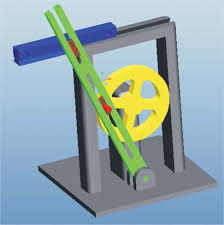
Crank and slotted lever quick return motion mechanism – Inversion of slider crank mechanism (connecting rod fixed).
This mechanism is mostly used in shaping machines, slotting machines and in rotary internal combustion engines. In this mechanism, the link AC (i.e. link 3) forming the turning pair is fixed, as shown in Fig. The link 3 corresponds to the connecting rod of a reciprocating steam engine. The driving crank CB revolves with uniform angular speed about the fixed centre C. A sliding block attached to the crank pin at B slides along the slotted bar AP and thus causes AP to oscillate about the pivoted point A. A short link PR transmits the motion from AP to the ram which carries the tool and reciprocates along the line of stroke R1R2. The line of stroke of the ram (i.e. R1R2) is perpendicular to AC produced.
We see that the angle β made by the forward or cutting stroke is greater than the angle α described by the return stroke. Since the crank rotates with uniform angular speed, therefore the return stroke is completed within shorter time. Thus it is called quick return motion mechanism.
In the extreme positions, AP1 and AP2 are tangential to the circle and the cutting tool is at the end of the stroke. The forward or cutting stroke occurs when the crank rotates from the position CB1 to CB2 (or through an angle β) in the clockwise direction. The return stroke occurs when the crank rotates from the position CB2 to CB1 (or through angle α) in the clockwise direction. Since the crank has uniform angular speed, therefore,

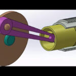
Pendulum pump or bull engine–Inversion of slider crank mechanism (slider fixed).
In this mechanism, the inversion is obtained by fixing the cylinder or link 4 (i.e. sliding pair), as shown in Fig. In this case, when the crank (link 2) rotates, the connecting rod (link 3) oscillates about a pin pivoted to the fixed link 4 at A and the piston attached to the piston rod (link 1) reciprocates. The duplex pump which is used to supply feed water to boilers have two pistons attached to link 1, as shown in Fig.