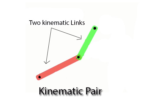
The two links or elements of a machine, when in contact with each other, are said to form a pair. If the relative motion between them is completely or successfully constrained (i.e. in a definite direction), the pair is known as kinematic pair.
Classification of kinematic pair
The kinematic pairs may be classified according to the following considerations:
(i) Based on nature of contact between elements:
(a) Lower pair. If the joint by which two members are connected has surface contact,the pair is known as lower pair. Eg. pin joints, shaft rotating in bush, slider in slider crank mechanism.

Lower pairs
(b)Higher pair. If the contact between the pairing elements takes place at a point oralong a line, such as in a ball bearing or between two gear teeth in contact, it is known as a higher pair.

Higher pairs
(ii)Based on relative motion between pairing elements:
(a) Siding pair. Sliding pair is constituted by two elements so connected that one isconstrained to have a sliding motion relative to the other. DOF = 1
(b)Turning pair (revolute pair). When connections of the two elements are such thatonly a constrained motion of rotation of one element with respect to the other is possible, the pair constitutes a turning pair. DOF = 1
(c) Cylindrical pair. If the relative motion between the pairing elements is thecombination of turning and sliding, then it is called as cylindrical pair. DOF = 2

| Sliding pair | Turning pair | Cylindrical pair |
(d)Rolling pair. When the pairing elements have rolling contact, the pair formed iscalled rolling pair. Eg. Bearings, Belt and pulley. DOF = 1

Ball bearing Belt and pulley
(e) Spherical pair. A spherical pair will have surface contact and three degrees offreedom. Eg. Ball and socket joint. DOF = 3
(f) Helical pair or screw pair. When the nature of contact between the elements of apair is such that one element can turn about the other by screw threads, it is known as screw pair. Eg. Nut and bolt. DOF = 1

Ball and socket joint Screw pair
(a) Sliding pair (prismatic pair) eg. piston and cylinder, crosshead and slides, tail stock on lathe bed.
(b) Turning pair (Revolute pair): eg: cycle wheel on axle, lathe spindle in head stock.
(c) Cylindrical pair: eg. shaft turning in journal bearing.
(d) Screw pair (Helical pair): eg. bolt and nut, lead screw of lathe with nut, screw jack.
(e) Spherical pair: eg. penholder on stand, castor balls.
(iii) Based on the nature of mechanical constraint.
(a) Closed pair. Elements of pairs held together mechanically due to their geometryconstitute a closed pair. They are also called form-closed or self-closed pair.
(b)  Unclosed or force closed pair. Elements of pairs held together by the action ofexternal forces constitute unclosed or force closed pair .Eg. Cam and follower.
Closed pair Force closed pair (cam & follower)