12.1 PIPES AND TUBES
Pipes and tubes are long cylindrical conduits (the L/D ratio of which is very large as compared to tanks or vessels) of a hollow material of uniform cross section through which liquid and gas can pass. Though the terms “pipes” and “tubes” are used interchangeably, pipes are of a larger diameter and are made of metal, e.g., steel, copper, brass, etc. Tubes are comparatively smaller in diameter and are usually non-metallic. Liquid and gases are transported through pipes connecting one tank to another, pump/ compressor discharges to processing units, unit to unit, from one plant to another plant, etc. Thus, small or long pipelines are inevitable for transporting fl uids. Liquid density does not change appreciably with pressure and is therefore known as incompressible fl uid. Gas density directly varies with pressure to a great extent and hence gases are called compressible fl uids. Liquids and liquifi ed gases are transported by pumps, whereas gases are transported by compressors. Pipe diameters as small as 1/8 in and as high as 36 in are commonly employed in refi neries and petrochemical plants. The wall thickness of a pipe is specifi ed by the schedule number, which is defi ned as
Schedule number = 1000*P∕S,
where P and S are the fl uid pressure carried in the pipe and the working stress of the material of the pipe wall, respectively. In practice, schedule numbers varying from 10 to 160 are commonly employed. Pipe diameters inside (i.d.) and outside (o.d.) and the thickness corresponding to various schedule numbers are available in standard tables as given in the Appendix. The greater the schedule number, the greater the wall thickness. Tubes are usually specifi ed by standard gauge numbers (British wire gauge number, BWG) where the wall thickness decreases with the increasing gauge numbers. A large number of tubes are used in heat exchangers where the tubes are specifi ed by the Tubular Exchangers Manufactures’ Association (TEMA) code. In fact, for hydrocarbon services, the American Petroleum Institute (API) codes are commonly employed. Therefore, when the selection of pipes for then for hydrocarbon services, the API codes should be consulted.
12.2 FITTINGS AND SUPPORTS
Fittings are shorter pieces of materials that are required for connecting pipes of the same or different diameters, connecting pipes leading in different directions without bending the pipes, providing multiple pipe connections, or closing a pipe end, etc. Examples of such fi ttings are bends, tee joints, elbow, etc., as shown in Figure 12.1.

Fittings are essential for connecting pipes with pumps, compressors, other machines, vessels, or equipment. These fi ttings may be joined by threading or by fl anges. Pipes running overhead are supported by hangers and suitable columns. Pipes may be laid on the surface or underground (humed or buried). For long pipelines, it may be desirable to lay the pipes in loops to avoid sudden expansion, contraction, or vibration of the pipe. Valves are installed on the pipes connecting two pipe pieces and for manipulating fl ow rates through a pipeline. Valves may be small or large, depending on the pipe diameter, and may be manually or mechanically operated. A control valve is a special type of valve that is driven by the actuator. Control valves are discussed in more detail in Chapter 13. When valves are tightly shut, fl ow between the connected pipes is isolated. Since valves may leak because of erosion or corrosion of the valve plugs and/or seat due to prolonged use, it may be necessary to provide blinds (tail or spectacle) in between the pipe and valve joints or additional pipe joints specially provided for blinding. Pipes may carry gas or liquid, be cold or hot, or be bare or insulated. Pipe lines carrying liquids having a tendency to freeze are usually provided with a steam coil running over the bare surface of the pipe and are known as steam-traced lines. The entire pipe and the steam-traced surface are further insulated to avoid condensation of steam. Hot pipes are also sometimes provided with a temperature safety fuse or valve (TSV) to avoid damage to the pipeline due to a sudden temperature rise on the pipe surface. Gases are usually transported through pipes under pressure with the help of compressor. Pressure safety valves are provided on these pipes to avoid bursting of the pipes.
12.2.1 CORROSION PROTECTION
The bare surface of pipes is exposed to oxide corrosion. Pipes are usually made of mild steel, which is vulnerable to oxide corrosion due to the galvanic action
of iron and atmospheric oxygen in the presence of moisture. Pipes are usually protected from corrosion by painting or galvanising or by applying an electrical charge from an outside source to the bare surface opposing the oxide corrosion, most commonly by the cathodic protection method. Pipes passing through an environment containing fl uids that may react with mild steel need special corrosion protection.
12.3 CRUDE OIL TRANSFER LINES
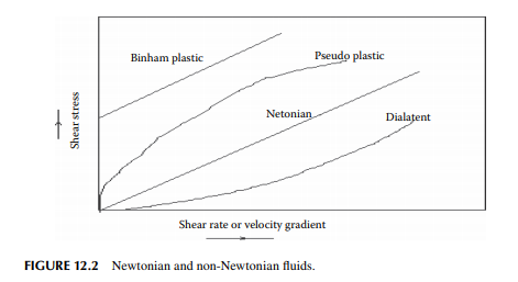
The density of liquid is almost unaffected by pressure, therefore liquid is called an incompressible fl uid. Crude oil is liquid but it may partially or completely solidify at low temperatures (even at ambient temperature) due to the presence of waxy hydrocarbons. In fact, crude below sea level or at the formation to the surface undergoes a variation of temperature due to the geothermal effect. According to Newton’s law of viscosity, the ratio of shear stress to shear rate is the viscosity and is unchanged during its fl ow while temperature is constant. Fluids that follow this rule are known as Newtonian fl uids. Many classes of crude oil do not follow this and are known as non-Newtonian fl uids. However, most of the varieties follow Newton’s law at elevated temperatures. Some varieties may behave as thixotropic or dilatent, etc. For non-Newtonian crudes, the viscosity term is replaced by formation the consistency index. Different types of fl uid viscous properties are presented in Figure 12.2.
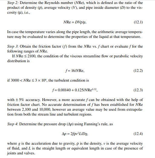
12.3.1 DESIGN STEPS FOR CRUDE PIPES
As most crudes behave like Newtonian fl uid at ambient temperature on the surface of Earth, the following steps can be extended for the design of pipelines. Step 1: Assume the diameter and length of the pipe and the necessary fi ttings and valves, if any, from a standard table of commercially available pipe dimensions.

consult the API standards applicable for hydrocarbon fl uids in order to decide on the material of construction and the thickness of the pipe. Other conditions, such as the reactive or corrosive atmosphere of both the outside and inside surfaces of the pipe, the operating temperature and pressure involved, etc., must be taken into account.
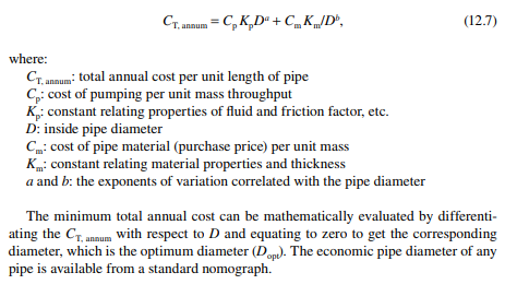
12.3.2 ECONOMIC PIPE DIAMETER
Since the pumping cost increases with an increase in pressure drop due to friction as the diameter is smaller and smaller, whereas the material cost of the pipe falls with the decreasing pipe diameter for the same length, economic consideration of the pipe diameter is essential. Thus,
Total cost per year = cost of pumping for the year + depreciation of pipe per year
where the cost of pumping for the same throughput in the year will increase with the smaller diameter pipe, i.e., it will be inversely proportional to pipe diameter, whereas depreciation of the pipe per year is a portion of the total cost of the pipe divided by the useful life span of the pipe material, which decreases with a decrease in the pipe diameter for the same throughput.
12.4 PRODUCT TRANSFER LINES
Liquifi ed gases, such as liquifi ed natural gas (LNG), liquifi ed petroleum gas (LPG), and liquid fuels, e.g., motor spirit, kerosene, diesel, furnace oil, etc., are also Newtonian liquids and pipe design steps will be as described in the previous section. Usually, white oils are transported through a same pipeline separating the products by maintaining pressure and a predetermined delivery time schedule. High pressure pumps will be required to maintain the fl ow as per schedule. Sticky, congealing, and viscous black oil products need separate steam-traced pipelines for transfer and are
usually not economical for long distance transport through pipelines. A pig, a tightly fi tting leather or polymer ball moved by the high pressure of liquid in the pipe, is required to separate black oil products in pipeline transport. Such a piping requires high pressure design as per the API and ANSI standard.
12.5 GAS TRANSFER LINES
The density of gas is a strong function of pressure and temperature. It increases with pressure and decreases with temperature. As density of gas varies appreciably with the variation of pressure, this is known as compressible fl uid, i.e., the volume of gas changes with pressure at a constant temperature. According to the ideal gas law, density (ρ) is related as

If the Mach number increases, the mechanical energy of transport is lost in the form of heat and sound as well. Therefore, it is desirable that the pipe should be designed so that the Mach number is less than unity. The pipe may handle hot or cold gas in a well insulated or a bare pipeline. A well-insulated pipe resembles an adiabatic condition whereas a bare pipe is non-adiabatic or isothermal. In the isothermal fl ow condition, the temperature being constant, density is a function of pressure only and the pressure may be evaluated by integrating it over the line. It is desirable that the average temperature and the pressure of the gas should be evaluated to determine its properties, such as viscosity, density, etc., avoiding complications due to variable properties throughout the length of the pipe. The design procedure will then assume the steps described in Section 12.4. Liquifi ed methane, better known as LNG, is usually transported by big tankers with the provision of an in situ refrigeration unit. However, compressed natural gas may be transported through a long pipeline at high pressure, but in gaseous form. Since the density is low, gaseous transfer may not be economical for a long pipeline.
12.6 PUMPS AND COMPRESSORS
Pumps and compressors are machines that deliver liquids and gases at the desired quantity and pressure through pipes connecting the storage to the delivery end, either short or long distances connected through pipelines. Gaseous fl uid or gas is transported by machineries, known as compressors, as gases are compressible fl uids. Thus, fl uid moving machines are classifi ed as pumps (for liquids) and compressors (for gases). These machines add necessary energy to make the fl uid move in the pipeline by one of the following methods:
1. Volumetric displacement by reciprocating pumps or compressors
2. Applying centrifugal force by centrifugal pumps or compressors
3. Mechanical impulse by axial fl ow pumps and compressors
4. Transfer of momentum by using another motive fl uid, by air lift or acid egg pumps
5. Applying electrical power and magnetic fl ux over an electrically conducting fl uid with an electromagnetic pump
12.6.1 CENTRIFUGAL PUMPS
The term “centrifugal” implies the centrifugal force generated by the blades of the impeller rotating at very high speeds used to deliver liquid to the pipeline. A typical centrifugal pump consists of a volute or a casing in which are housed a number of s-shaped impeller blades that look like a fan. Liquid enters the eye of the pump by gravity or due to the inlet or suction line pressure of the liquid. As the blade rotates, liquid from the eye of the pump moves to the tip of the blade and attains the kinetic energy imparted by the tip and fi nally strikes the delivery end of the volute. At the delivery end, kinetic energy is converted to pressure and thus the liquid discharges through the delivery end at high pressure energy or head. Such a centrifugal pump is shown in Figure 12.3. If the delivery end is shut off, i.e., there is no discharge from the pump, maximum pressure will be generated. While the delivery end is opened,
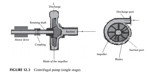
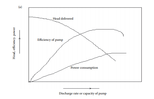
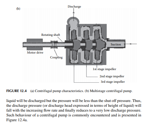


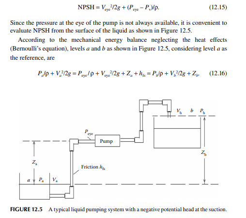
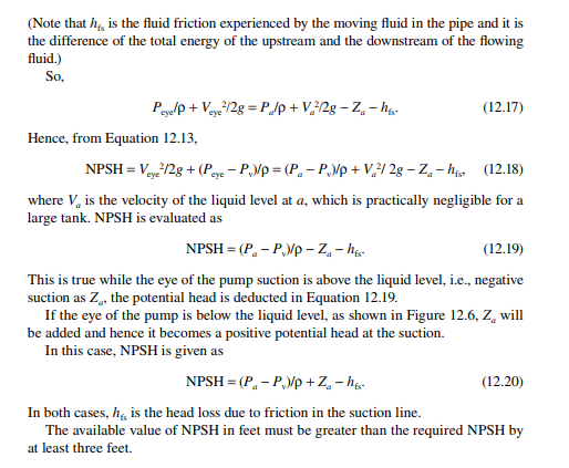
the discharged amount. If the volute becomes dry or fi lled with vapour or gas, the impeller will not be able to deliver the fl ow rate as the density of the gas is too small to be lifted by centrifugal force. If the volute is partially fi lled, the pump will not be able to discharge because the liquid will be returned back to the volute, causing knocking, which may even damage the impeller blades. Hence, it is essential that the volute of the pump must be fi lled before starting. Self-priming pumps are also available in which provision is made within the volute and the impeller such that gas is expelled at the starting of the pump, which then discharges the liquid when the self-priming is complete. The formation of vapour or low suction pressure causes cavitations, which result in no discharge, as is the situation with an unprimed pump. Cavitation may occur if the pressure at the suction port is lower than that required suction head for the pump. Theoretically, the available suction head should be greater than the desired (fi xed by the pump manufacturer) suction head. The available suction head is calculated from the pressure head after adding the kinetic head at the eye and deducting the vapour pressure head. This calculated head is usually expressed as the net positive suction head (NPSH). Thus, if the average velocity and static pressure at the eye of a pump are Veye and Peye, respectively, and the vapour pressure is Pv, then NPSH is given as

12.6.2 POSITIVE DISPLACEMENT PUMPS
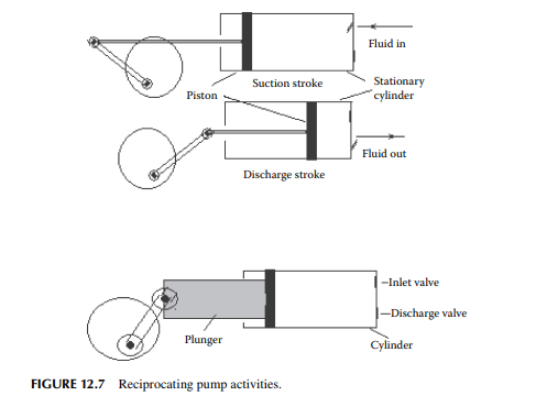
These pumps add energy by direct pressure to the fl uid or by displacement of the fl uid (positive displacement). Two groups of pumps fall into these categories— reciprocating and rotary. In the reciprocating pump, force is exerted by a piston compressing the fl uid contained in a cylindrical chamber. During suction stroke, the piston depressurises the chamber and allows fl uid to enter the chamber, which is then pressurised, in the discharge stroke, to the desired pressure head followed by delivery of the fl uid. Thus, suction stroke and discharge stroke complete a cycle, where half the cycle is for suction and the other half is for delivery of the fl uid. Pumps that deliver fl uid in half the cycle are known as single acting or stroke or single cylinder pumps. If two cylinders are connected in such a way that one cylinder discharges while the other completes the suction stroke and thus the delivery of fl uid occurs in a single cycle, this type of pump is called a two stroke or double acting or two cylinder pump. For a large pressure head with a small capacity, reciprocating pumps are suitable. For very high pressure with very small capacity, usually the dozing pumps are equipped with a plunger in place of a piston, as shown in Figure 12.7. These pumps are not suitable for sticky fl uids and slurries, which may damage the cylinder and/or the piston. However, viscous but clear, even molten, liquid may be pumped without damage. Corrosive acid or similar chemicals should not be pumped by piston pumps. However, a diaphragm is used to replace the piston and cylinder (Figure 12.8)
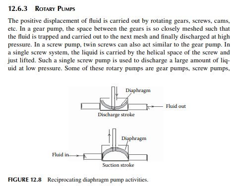
lobe pumps, cam pumps, etc. Gear pumps that consist of two gears in close mesh directly pushes the fl uid trapped in between them. All these pumps are suitable for viscous and sticky liquids. Diaphragm pumps can be used to deliver slurries and corrosive liquids. In a screw pump the helical surface of the shaft pushes the fluid. Screw pumps are widely used in wastewater treatment plants to lift a large quantity of water.
12.6.4 COMPRESSORS
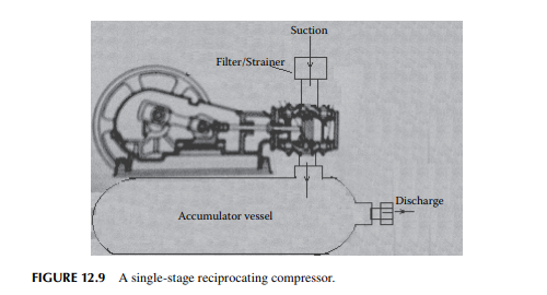
Gases are compressed from their suction pressure to the discharged pressure either by centrifugal or reciprocating compressors. These are also available as single stage and multistage compressors. During compression, heat is developed (it is to be noted that heat is generated due to adiabatic compression and also the mechanical and fl uid friction within the moving parts of the compressor), which increases the temperature of the gas, causing density reduction from that in the suction. If this heat is not removed (adiabatic), compressed gas will attain a high temperature causing low delivery rate as far as the mass fl ow rate is concerned. Therefore, the work required to deliver the same mass fl ow rate will be more for such an adiabatic condition as compared to an isothermal condition when heat is removed to bring the temperature of gas to the suction temperature. In fact, this is easier said than done because of the resistance to heat transfer from compressed gas to cooling fl uid. Practically, the temperature of the compressed gas will be between the adiabatic (while no heat is removed) and isothermal (while all heat is removed) temperature, which is also known as the polytropic (both adiabatic and isothermal conditions) temperature. For a multistage compressor, a cooling arrangement is desirable in each stage, known as the interstage cooler (stage cooler), to reduce the power consumption for a given mass fl ow rate of the gas. A single-stage reciprocating compressor is shown in Figure 12.9. An accumulator