3.1 CRUDE OIL RECEIVING
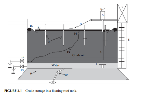
In a refi nery, crude oil is received and stored in a fl oating roof tank. The roof is made of compartmented deck or pontoon fl oating over the oil to avoid loss of hydrocarbon vapours of dissolved hydrocarbon gases and low boiling fractions present in crude oil. The fl oating roof also fl oats up and down to compensate for the breathing operations during pumping in and out of the tank thereby safeguarding the loss of vapours and ingress of atmospheric air into the tank. A fl oating roof storage tank of crude oil is shown in Figure 3.1, where a fl oating roof (1), made in the form of a ship’s deck, fl oats over the crude oil stored. As the vapour is formed, fl oating roof does not allow the vapour to leak into the atmosphere, thereby avoiding loss. During low level in the tank the roof is supported by legs (2) while it rests on the tank bottom. A dip pipe (4) is provided to measure the level of crude stored, through a dip hatch (5) with a cover (6). The level of liquid in the tank or dip can be manually measured with a graduated dip tape by climbing onto the tank from the operating platform (7) via a ladder (8). A manual inspection using a swing ladder (3) onto the surface of the fl oating roof can be done for deck compartments, the rolling seals (16), and the roof drain (14) connected with a fl exible steel pipe, which is mobile with the roof. Crude oil received from tank cars, pipelines, or from tankers (ship) may contain much water either carried with the cargo or due to fl ushing of the receiving line. This water must settle in the receiving tank before oil accounting is started. Temperature, oil cut, water cut, and the density of the sample crude are the most important parameters in determining the quantity of oil received. After the quantity and valuation of oil are established, the water in the tank must be drained. Steam coils and side mixers are usually provided near the bottom of the receiving tank to homogenise the crude layers before processing. However, water and salt, which do not settle in the tank, can only be removed by desalting located within the battery limit of the crude distillation unit.
3.2 DESALTING OF CRUDE OIL
Crude oil received in a refi nery contains much water, salts, clay, and sand, which do not settle in the tank and are desalter at the beginning of the refi ning operations. The amount of water and settleable solids present in crude oil is indicated by bottom sediment and water (BSW) analysis. The presence of salts of magnesium, sodium, alkaline earth metals in crude oil varies from crude to crude. These salts are dissolved 50 Fundamentals of
in water associated and entrained with crude oil from the drilling fl uids or wash water from the crude-carrying vessels. Salts in the presence of water are responsible for corrosion. For example, chloride salts of magnesium generate hydrochloric acid at a temperature above 150°C and may cause severe corrosion both in the liquid and vapour phases. The modern method of electrical desalting removes water and the dissolved salts simultaneously from crude oil. A modern electric desalter is shown in Figure 3.2, where crude oil enters the bottom of a horizontal vessel provided with two fl at electrodes supplied with a very high voltage (20–33 kV AC). Crude containing salt and water is mixed with fresh demineralised water (DM water) through a mixing valve at the bottom portion of the vessel in order to dissolve salts to the aqueous phase. The optimum temperature for solubilising the salts to the aqueous phase is 120°C–130°C, hence crude must be preheated to this temperature before it enters the desalter. Crude, water, and salt travel upward as an emulsifi ed mixture and are brought in contact with the fl at electrodes. Drops of water are ionised by electric charge and coalesce to form bigger drops of water, which then fall by gravity toward the bottom of the vessel. Thus, emulsion is broken as long as the crude–water mixture is in contact with the electrodes. De-emulsifying agents are also injected in small amounts to break the unbroken emulsion. The practice of electric desalting can reduce the salt content by 90%–98%. Single or multiple desalters in a series may be employed depending on the concentration of salt in the incoming crude. At the desalting temperature, low boiling hydrocarbons may vaporise and the desalting operation is affected. This also causes cavitation to the discharging pump at the exit of the desalter. To avoid vaporisation, the drum pressure is monitored and controlled by a pressure controller, which senses the pressure through a pressure transmitter and manipulates the feed fl ow rate to and from the desalter. Pressure in the drum is usually maintained at a pressure
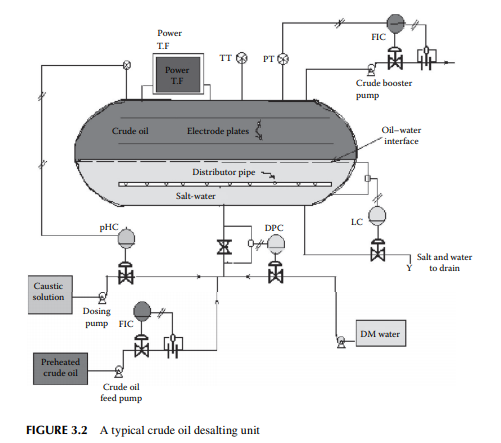
slightly above the vapour pressure of mixed hydrocarbon gases, usually 8–10 kg/cm2, to maintain the liquid phase, if the pressure increases above this due to vaporisation, vapours will pop through a pressure safety valve leading to the crude distillation column and the power supply to the transformer is automatically switched off to avoid an accident. Formation of hydrochloric acid from chloride salts and the presence of organic acids in crude oil may cause severe corrosion in the desalter drum. Hence, a caustic solution is injected with the incoming crude and the pH of the aqueous phase is monitored and controlled to maintain a pH near 7. The water level in the desalter is controlled such that the water level should not reach the electrodes, which may cause a short circuit between them as water is a good conductor of electricity. An interface level transmitter senses the water–oil interface level and sends an alarm signal if the level is high or low and it automatically switches off the power supply in case the water rises above a high level. A low level of water may cause poor desalting and may allow carryover of crude oil with discharged brine to drain.
3.3 DISTILLATION AND STRIPPING
Distillation of crude oil is carried out at atmospheric pressure and under vacuum. Low boiling fractions vaporise at atmospheric pressure up to a temperature below
400°C without cracking the hydrocarbon compounds. High boiling fractions are vaporised under vacuum at a temperature much lower than 400°C and cracking is avoided. Thus, all the low and high boiling fractions of crude oil are separated by atmospheric distillation followed by vacuum distillation without cracking or degradation of the original hydrocarbons present in crude oil. After the removal of oil fractions, the vacuum residue left requires solvent extraction (known as deasphalting) to recover the remaining valuable petroleum fraction. Atmospheric distillates are the major source of petroleum fuels and vacuum distillates are the source of fuels, wax, lubricating oil base stocks, bitumen, petroleum cokes, etc., mainly by secondary treatments like extraction, thermal, and catalytic treatments.
3.3.1 ATMOSPHERIC DISTILLATION
Crude oil from the desalter is heated in a train of heat exchangers up to a temperature of 250°C–260°C and further by a tube-still heater (also known as a pipe-still furnace) to a temperature of 350°C–360°C. Hot crude is then fl ashed into a distillation column, which is a tall, multiplated cylindrical vessel that separates the petroleum fractions according to the differences in volatility. Top pressure is maintained at 1.2–1.5 atm such that the distillation operation can be carried out at a pressure close to atmospheric pressure and for this reason this column is also known as the atmospheric distillation column. Vapours from the top of the column, consisting of hydrocarbon gases and naphtha, emerge at a temperature of 120°C–130°C. The vapour stream associated with steam used in the column bottom and the side strippers are condensed by a water cooler and the liquid is collected in a vessel (known as a refl ux drum) situated at the top of the column. Part of this overhead liquid (oil phase only) is returned to the top plate of the column as overhead refl ux and the rest of the liquid is drawn and sent to a stabilizer column which separates gases from liquid naphtha. A few plates below the top plate, the kerosene fraction is drawn at a draw temperature of 190°C–200°C. A part of this fraction is returned to the column after it is cooled by a heat exchanger. This cooled returned stream is known as circulating refl ux and is essential to control the heat load in the column. The rest of the draw is passed to a side stripper where steam is used to strip out the undesirable low boiling fractions to maintain the desirable fl ash point of kerosene fraction, which is then further cooled and sent to a storage tank as raw kerosene, also known as straight run kerosene, which boils in the range of 140°C–270°C. A few plates below the kerosene draw plate, the diesel fraction (also known as atmospheric gas oil or straight run diesel or gas oil) is drawn at a temperature of 280°C–300°C. After cooling, part of this is returned to the column as circulating refl ux and the rest is steam stripped through a side stripper, like kerosene, to adjust the fl ash point. This diesel fraction, with a boiling range of 270°C–340°C, from the stripper is then cooled and sent to storage. In some refi neries, jute batching oil (JBO), which is an intermediate cut between diesel and the bottom residue, is also drawn at a draw temperature of 300°C–330°C followed by steam stripping. Residual oil drawn from the bottom of the column is known as reduced crude oil (RCO), topped crude, or long residue. The temperature of the stream at the bottom reaches around 340°C–350°C, well below the cracking temperature of oil. RCO
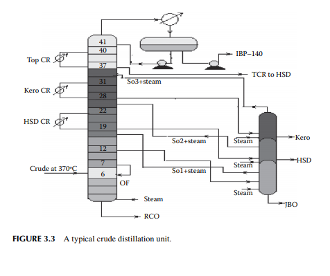
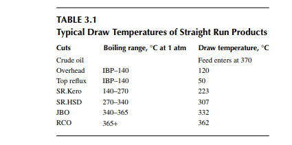
is a brown to deep chocolate-coloured stream containing high boiling fractions that cannot be vaporised at the prevailing temperature and atmospheric pressure of the column without cracking. Since depression of the boiling point occurs as the system pressure is reduced, boiling fractions remaining in the atmospheric residue are, therefore, distilled under vacuum in a separate column (known as the vacuum distillation column) where high boiling fractions are separated and collected as vacuum distillates. A typical atmospheric distillation column (containing 41 plates), where the hot feed crude oil is fl ashed in the fi fth plate, producing top distillate (IBP–140°C cut), straight run kerosene (140°C–270°C cut), straight run diesel (270°C–340°C cut), JBO (340°C–365°C cut), and the bottom residue (RCO, 365°C + cut), is shown in Figure 3.3. The top product goes to the gas and naphtha separation plant directly from the column. Kerosene, diesel, and JBO from the strippers are sent to fi xed roof storage tanks. By introducing the liquid from the seventh plate back to the fi fth plate, 4%–5% of the feed is over fl ashed. Overfl ash helps in further removal of heavier components carried over with the lighter stream. Part of the RCO from the bottom of the column goes to a vacuum distillation unit and the rest goes to a steam-heated fi xed roof storage tank. The pipeline carrying the RCO to a vacuum distillation unit is well insulated and steam traced to avoid congealing of the product in the line. A temperature between 180°C and 200°C in the transfer line is usually maintained. Typical draw temperatures of the straight run distillates from an atmospheric distillation column are listed in Table 3.1
3.4 STABILISATION
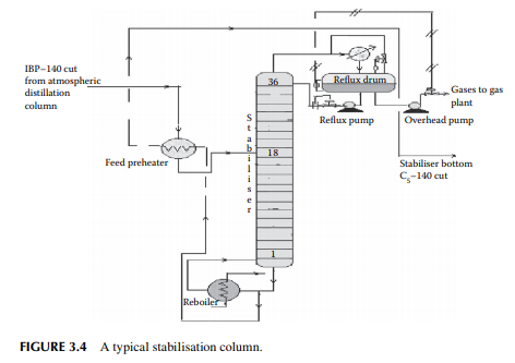
The top product from the atmospheric distillation column (IBP–140°C cut) is a mixture of hydrocarbon gases, e.g., methane, ethane, propane, butane, and naphtha vapours. Methane, ethane, propane, and butane exist in gaseous form, whereas naphtha vapours liquify at ambient temperature and atmospheric pressure. Hence, if the overhead product is kept at atmospheric pressure, these valuable liquifi able fuel gases will be lost to the atmosphere. The initial boiling point (IBP) of this mixture will vary due to the relative presence of these gases. These gases are easily separated from naphtha by distillation in a multiplated column where the top product is the mixture of gases containing methane to butanes and the bottom product is stabilised naphtha boiling in the range of C5–140°C. A typical stabiliser column is shown in Figure 3.4.
3.5 AMINE ABSORPTION
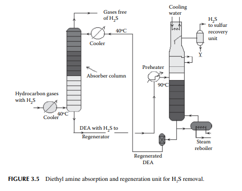
Gases from the stabiliser go to a gas plant where hydrogen sulfi de associated with hydrocarbons is removed by solvent extraction, usually by diethyl amine (DEA) solution. In a plated tower, the solvent fl ows down and the gases fl ow up the column countercurrently. Used amine solvent containing hydrogen sulfi de emerges from the bottom of the tower and the top of the column produces hydrocarbon gases free of hydrogen sulfi de. The amine solution containing hydrogen sulfi de is regenerated in a separate steam stripper. A typical amine absorber and a regenerator are shown in Figure 3.5.
3.6 DE-ETHANISER
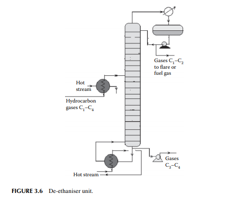
A gas mixture from the amine wash column enters a de-ethaniser column where methane and ethane are separated from the propane and butanes by distillation. This is a distillation column where a preheated feed gas mixture is introduced in the tower, reboiled by a heater at the bottom of the column, and refl uxed by the top product from the refl ux drum located at the top of the tower to separate the methane and ethane gases from the rest. The top product from this column is sent to a fuel gas system for the furnaces used in the refi nery. However, top gases may also be used as a source of petrochemicals and hydrogen. The bottom product is a mixture of propane and butanes that are sent to a meroxing unit for the removal of mercaptans. A typical de-ethaniser is shown in Figure 3.6
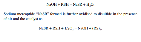
3.7 MEROXING AND CAUSTIC WASH
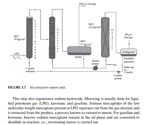
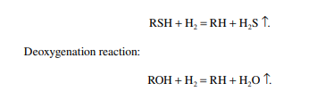
Merox is an abbreviation of the words “mercaptan oxidation,” which is done catalytically in a packed bed reactor. Mercaptans are a sulfur compound of hydrocarbons and are designated as RSH, where “R” is the alkyl radical, “S” is the sulfur atom, and “H” is the hydrogen atom. Mercaptans are highly corrosive, hence their presence in petroleum products is not desirable. Mercaptans can be extracted by a caustic solution, a process known as extractive merox (as shown in Figure 3.7). Mercaptans can also be catalytically converted to disulfi des (cobalt salt in the form of a chelate compound as the catalyst containing in a charcoal packed bed). Disulfi de (RS)2 are not corrosive as mercaptans and remain with the product. This type of treatment is called sweetening merox (as shown in Figure 3.8). The following reaction takes place in a caustic solution.
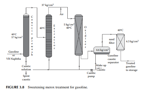
Though meroxing is a convenient method for reducing the corrosiveness of the product, both mercaptans and disulfi des produce sulfur compounds of oxygen (SOx), which is a major pollutant to the environment, therefore, meroxing is replaced by catalytic hydrodesulfurisation in modern refi neries.
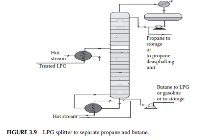
3.8 LIQUIFIED PETROLEUM GAS SPLITTER
Liquifi ed petroleum gas (LPG) mainly contains a mixture of propane and butane with traces of methane and ethane left after de-ethanisation. Propane and butane can be separated from LPG by distillation in a plated tower, the top product is enriched propane and the bottom product is butane. In refi neries that use propane as the solvent for the propane deasphalting unit or as a refrigerant, they can obtain their propane requirement from such a distillation column, commonly known as an LPG splitter. Butane is either recycled to LPG or blended in gasoline to adjust the Reid vapour pressure (RVP). A typical LPG splitter column is shown in Figure 3.9.
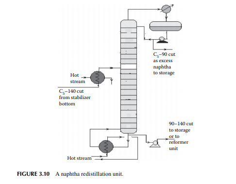
3.9 NAPHTHA REDISTILLATION
As already mentioned in Section 3.3, a naphtha stream is obtained from the stabiliser bottom, which is normally liquid boiled in the range of C5–140°C, which means hydrocarbons having carbon number fi ve and hydrocarbons boiling up to 140°C are present in the mixture. This is further separated into two fractions in a column where the top is the lighter fraction, C5–90°C, and the bottom is 90°C–140°C. This lighter fraction is suitable for petrochemical plants in the production of olefi ns and hydrogen because of the presence of paraffi nic hydrocarbons, whereas the heavier naphtha is suitable for the production of high octane gasoline and valuable petrochemicals like benzene (B), toluene (T), and xylenes (X). A typical naphtha redistillation column is shown in Figure 3.10.
3.10 NAPHTHA PRETREATMENT
A catalytic reforming unit uses platinum as the catalyst to convert naphtha into high octane gasoline or aromatics. As a platinum catalyst is easily poisoned by the presence of sulfur, oxygen, nitrogen, and metallic components, it is essential to pretreat naphtha before reforming. This, in fact, is done simultaneously in a catalytic hydrogen pretreatment reactor. Naphtha stream, i.e., 90°C–140°C fraction, from the naphtha redistillation column is usually desulfurised in a catalytic hydrogenation unit and is then sent to a platinum reforming unit where high octane gasoline or aromatics (BTX) are produced. In this unit, naphtha is preheated by a train of heat exchangers and further heated in a pipe-still heater to a temperature of 350°C in the presence of hydrogen under a pressure of 20–25 kg/cm2 over a catalyst (Co-Mo sulfi des supported on alumina) packed bed reactor.
The following types of reactions take place in the reactor.
Desulfurisation reaction:
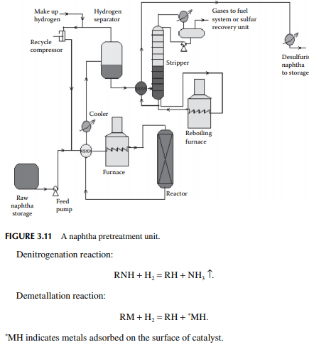
The feed naphtha is premixed with hydrogen and heated by preheaters and a tubestill heater to raise the temperature up to 350°C at a pressure of 20–25 kg/cm2. The product mixture from the reactor is cooled to 50°C and fl ashed in a separator vessel to release unreacted hydrogen, which is then recycled back to the reactor. The product mixture containing hydrocarbon gases (C1–C4), hydrogen sulfi de, ammonia, moisture, etc., are steam stripped in a plated column. Desulfurised naphtha comes out as the bottom product which is further cooled before it is sent to storage. A fl ow sheet of naphtha pretreatment is shown in Figure 3.11.
3.11 NAPHTHA PLATINUM REFORMING (PLATFORMING)
Desulfurised naphtha (90°C–140°C) is catalytically converted to high octane gasoline by the reaction of a platinum (now platinum–rhenium) catalyst in a reactor in a hydrogen environment. This type of treatment is also known as platforming. The major reactions involved during platforming are dehydrogenation, isomerisation,
and dehydrocyclisation along with a small amount of hydrocracking and hydrogenation reactions. The following are examples.
1. Dehydrogenation of paraffi ns and naphthenes: n-paraffi ns = alkenes + hydrogen naphthenes = aromatics + hydrogen These reactions are endothermic.
2. Dehydrocyclisation of paraffi ns: n-paraffi ns = naphthenes + hydrogen This reaction is also endothermic.
3. Isomerisation of paraffi ns: n-paraffi ns = i-paraffi ns This reaction is nearly thermo-neutral.
4. Hydrocracking: n-paraffi ns + hydrogen = hydrocarbon gases + lighter paraffi ns naphthenes + hydrogen = hydrocarbon gases + lighter naphthenes These reactions are exothermic.
5. Hydrogenation alkenes + hydrogen = alkanes aromatics + hydrogen = naphthenes These reactions are exothermic.
6. Coking reactions: hydrocarbons = carbon or cokes
Desulfurised naphtha and hydrogen are mixed and preheated by heat exchangers followed by heating in a tube-still furnace to raise the temperature of the vapour mixture to around 500°C. The reaction temperature is 470°C at the start of the run (SOR), i.e., when the catalyst is fresh or regenerated. A traditional reformer catalyst contains 0.3–0.35% wt of platinum. Since, during the reaction, coke formation takes place over the surface of the catalyst, the reactivity of the catalyst comes down and the temperature has to be raised to maintain the uniform reactivity. When the catalyst is used for about a year, the temperature has to be maintained near 520°C. The temperature is not raised further to avoid permanent damage to the catalyst. However, deactivation due to coke laydown is temporary and can be removed by burning the coke in the presence of air during regeneration. However, damage due to high temperatures above 600°C is permanent because of the sintering of the catalyst; hence the temperature at the end of the run (EOR) is never allowed to increase above 520°C. Traces of sulfur, nitrogen, and oxygen present in the feed naphtha permanently deactivate the catalyst and that is why naphtha pretreatment (as discussed earlier) is carried out before reforming. In order to reduce coke formation, it is essential to maintain hydrogen circulation at a desired partial pressure. Usually a minimum of 5 mol of hydrogen per mole of feed naphtha must be maintained during the reaction. The total pressure of the system is about 25–30 kg/cm2. Usually, three reactors in a series are employed while regeneration is carried out for all the reactors after complete shutdown of the unit. Alternatively, four reactors may be employed while three reactors, in fact, are in service and the fourth reactor (swing reactor) is
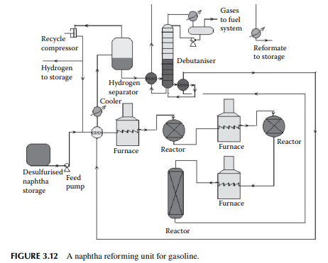
taken out for regeneration. This unit does not require complete shut down and hence production is not affected. A typical reforming unit is shown in Figure 3.12. Three reactors are used in this fl ow sheet, the fi rst two are spherical in shape while the last one is cylindrical. The catalyst is loaded and distributed in these reactors in the ratio of 15:35:60 by percent weight of the total weight of the catalyst loaded, respectively. Since the overall reactions are endothermic in nature, the product temperature falls while exiting from a reactor and is reheated by the intermediate furnace before it enters the second and third reactor. Finally, the product mixture is cooled and separated from hydrogen by fl ashing in a vessel at a temperature of 50°C. Hydrogen from this vessel is partly recycled back to the reactors and a part is sent to other hydrogenconsuming units in the refi nery. The product from the bottom of the separator vessel is sent to a plated column to separate the butane and lighter hydrocarbons from the fi nal product, known as the debutanised reformate, which is cooled before storage.
3.12 KEROSENE HYDRODESULFURISATION
Straight run kerosene (SKO, ATF, MTO, RTF) fractions from the atmospheric unit contain sulfur as compounds of hydrocarbons. This sulfur is catalytically hydrogenated to hydrogen sulfi de and is thus removed from the kerosene fractions. This process is similar to the naphtha pretreatment process. Here, kerosene feed is mixed with hydrogen and preheated to 250°C–260°C followed by heating in a tube-still furnace to raise the temperature further to around 350°C. This hot mixture then
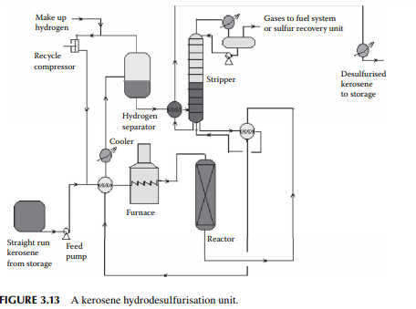
enters a fi xed bed reactor containing a bed of cobalt or nickel-molybdenum catalysts. The products are hydrogen sulfi de, ammonia, and moisture, which are formed due to reactions with hydrogen and sulfur, nitrogen, and oxygen-containing hydrocarbons. A small amount of C1–C5 hydrocarbon gases may also be formed due to the cracking reactions. Excess hydrogen is always used to maintain suffi cient partial pressure of hydrogen for the reactions and also to suppress coke formation. Excess hydrogen is separated from the cooled products in a high-pressure separator drum and recycled. Desulfurised liquid kerosene, containing dissolved hydrogen sulfi de, moisture, ammonia, and hydrocarbon gases, is then stripped off in a stabiliser column. Gases from the top of this stabiliser may be treated in an amine absorption unit before it is used as a refi nery fuel. A fl owsheet diagram of a kerosene hydrodesulfurisation unit (KHDS) is shown in Figure 3.13. Usually, hydrogen consumption in a KHDS unit and the naphtha pretreatment unit is not much, however, hydrogen generated in a reforming unit is more than suffi cient and, in fact, excess is used elsewhere, as in the lube hydrofi nishing unit in a refi nery.
3.13 DIESEL HYDRODESULFURISATION
The main ingredient of diesel oil is the straight run atmospheric gas oil, i.e., the straight run diesel fraction. However, many other fractions, such as distillates from a vacuum distillation unit (vacuum gas oil (VGO), spindle oil (SO) fraction), by-products from a vis-breaking unit (VB gas oil), light cycle oil from a fl uid catalytic cracking (FCC) unit, and heavy naphtha fractions, join in a diesel pool. Thus, diesel contains a lot of sulfur that is removed in a catalytic hydrogenation unit similar to the KHDS unit
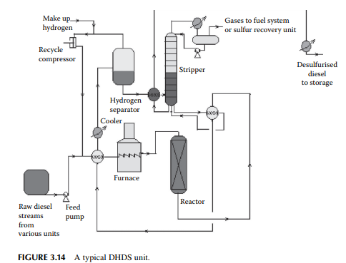
described. The only difference is that higher hydrogen pressure (about 40–50 kg/cm2 ) is required to remove sulfur from the heavier sulfur-containing hydrocarbons present in the diesel oil. Because of this, mild hydrocracking reactions may occur and produce cracked C1–C5 hydrocarbon gases. High-pressure separation of hydrogen and stabilisation of the fi nal product is also similar to the KHDS unit. A typical diesel hydrodesulfurisation (DHDS) unit is shown in Figure 3.14. Since hydrogen consumption is larger and variable with the rate of production of diesel fractions, a separate hydrogen generation unit (which is discussed in detail elsewhere in this book) is required.
3.14 VACUUM DISTILLATION
As already mentioned in Section 3.1, vacuum distillation of the atmospheric residue yields additional and valuable distillates, which could otherwise be thermally destroyed if further distillation was attempted at atmospheric pressure and above. A typical vacuum distillation unit is shown in Figure 3.15. Hot RCO either from the steam-heated storage tank or from the bottom of the atmospheric distillation column is pumped through a series of preheaters (heat exchanger train) followed by heating in a pipe-still heater to raise the temperature to 360°C–370°C. This hot stream is then fl ashed in a multiplated distillation column where vacuum (below atmospheric pressure) is maintained by steam ejectors by medium pressure superheated steam as the motive fl uid that entrains the top hydrocarbon vapours, which are condensed by water coolers. Usually, three numbers of ejectors are used; the fi rst stage sends the uncondensed vapour to the second stage followed by condensation. The uncondensed vapour then enters the third stage followed
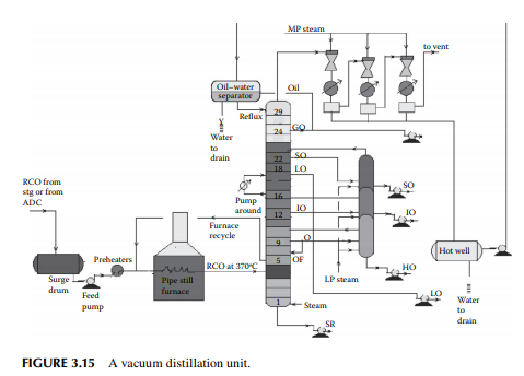
by condensation and the uncondensed vapour from the third stage is vented out through a fl are or stack. A vacuum of 30–40 mm of mercury is maintained at the top of the column and 100–120 mm at the bottom. Condensates from these ejectors are collected in a drum, known as a hot well. The oily layer is then sent to an oil–water separator vessel from which oil is drawn as vacuum gas oil (VGO), part of which is sent to the column as the refl ux and the rest to storage. Condensates from the hot well and the separator drum are drained to the sewer or water collection system. A few plates below the top plate of the column, an additional VGO is drawn and sent to the diesel/gas oil pool. SO is the next vacuum distillate, which is drawn a few plates below the gas oil draw plate. Similarly, the other vacuum distillates drawn from the plates below are light oil (LO), intermediate oil (IO), and heavy oil (HO) in this sequence. LO is sent to the vis-breaking unit for the production of low viscous fuel oils, whereas SO, IO, and HO distillates are further stripped in a side stripper by steam to remove the lighter components to adjust the fl ash points. The bottom residue from the tower is called the short residue (SR), which is stripped by the bottom steam followed by cooling through a steam generator and sent for storage in the deasphalting unit. A portion of the hot vacuum distillate is drawn from the column and returned back after cooling to control the heat load of the column. This stream is called the pump around. Unlike circulating refl uxes in the atmospheric column, pump around is only one stream in the vacuum column. To aid washing of the HO fraction, 4%–5% of the feed RCO is overfl ashed. It is to be mentioned that SO, IO, and HO are the lube oil base stocks (LOBS), which are the main ingredients of lubricating oils in the market. Valuable lube oil stock, known as bright stock, is obtained from the SR by solvent deasphalting. However, the quality of vacuum distillates varies from crude to crude and, as a result, many crudes may not yield LOBS, but are converted to fuel products. It is commonly found that most of the Middle East or Gulf crudes are
3.15 SOLVENT EXTRACTION
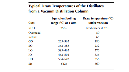
Vacuum distillates (SO, IO, HO) and also the deasphalted oil from the residue (bright stock) are suitable for the production of LOBS, which are the main ingredients of fi nished lubes (which are, in fact, obtained by blending metallic soaps and additives along with the LOBS). In order to meet the desired quality of lubes, certain properties, such as viscosity, viscosity index, pour point, fl ash point, carbon residue, foaming tendencies, sulfur content, and colour, must be adjusted by secondary processing after vacuum distillation. Solvent extraction is the traditional process for adjusting the viscosity index of the oil by partially removing the aromatic hydrocarbons, which are high viscosity and low viscosity index components. Solvents, such as phenol, furfural, and nitro methyl pyrolodine (NMP), are commonly used in refi neries. These solvents have a high affi nity to aromatic hydrocarbons, which are solubilised by these and form a different layer or phase, called extract. The rest of the oil lean with aromatics are separated as the raffi nate. The amount of separation of aromatic hydrocarbons by the solvent depends mainly on the operating parameters, such as solvent-to-oil ratio, temperature, partial solubility with the nonaromatic compounds present in the oil, or selectivity. Solvent and oil are contacted in a plated column usually in a rotating disc contactor (RDC) type gentle agitator provided over the plates through a common rotating shaft. The down coming stream is gradually enriched with aromatics and fi nally drawn from the bottom of the column as the extract. The uprising stream is gradually lean with aromatics and rich with paraffi ns and other non-aromatics and fi nally emerges as the raffi nate stream. In fact, complete removal of aromatics from oil is not desirable as aromatics are the main contributors to the viscosity of the oil and hence removal of aromatics is carefully selected based on the required adjustment of the viscosity and viscosity index of the fi nal product. Solvent from both the extract and raffi nate phases is recovered by steam strippers and is recycled back to the extraction column. A typical furfural extraction unit is shown in Figure 3.16.
3.16 PROPANE DEASPHALTING
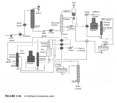
Liquid propane is a good solvent for hydrocarbon oil and mainly rejects heavy hydrocarbons (asphaltenes) and non-hydrocarbons present as asphalt in the vacuum residue. Hence, propane is used as a solvent for extracting oil from vacuum residue or SR. The extracted oil is known as deasphalted oil, which is suitable LOBS (Lube oil base stock) for making high viscous lubricants, the viscosity index is then corrected by selective solvent extraction of aromatics, as discussed in the previous section. A deasphalting column is also a plated tower where the down coming stream becomes rich with asphalt and emerges from the bottom of the tower as the raffi nate and uprising stream becomes rich with the deasphalted oil and fi nally emerges as the extract. Propane is separated by vaporising both the extract and raffi nate streams in separate steam strippers. A typical propane deasphalting unit is shown in Figure 3.17.
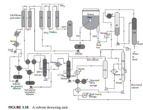
3.17 SOLVENT DEWAXING
Solvent-treated vacuum distillates and deasphalted oil, as discussed in the previous sections, are further treated to adjust the pour point of the oil. Normal paraffi nic hydrocarbons present in the oil have a high solidifi cation temperature and form wax as the solid or semi-solid mass of hydrocarbons. There are paraffi nic molecules
that can solidify even at room temperature. Since lubricating oil is used at various temperatures, ranging from very low to very high temperatures, it is essential that lubricating oil does not solidify in this range of temperatures. Hence, the pour point (a few degrees above the solidifi cation temperature) of lube oil must be low. Though paraffi ns (mainly normal varieties) are responsible for wax formation, wax is defi ned as the hydrocarbon matter that solidifi es at a temperature below –20°C (or the lowest temperature of the environment determined by the usage). Wax-forming hydrocarbons are selectively removed by low temperature freezing and separation. This is usually carried out by mixing the feed oil with a solvent, such as methyl ethyl ketone, benzene, or toluene, mixed in various proportions to prevent crystallisation of the wax-forming molecules in the precoolers and chillers, until they are separated from the solvents along with the desired oil components through a fi lter. A typical dewaxing plant, as shown in Figure 3.18, uses a vacuum drum fi lter where the solvent–oil mixture is sprayed over a fi lter cloth on a rotary drum enclosed in an inert atmosphere. The wax crystallises over the fi lter cloth and is scraped out with a scraping blade (also known as doctor’s knife) in a continuous manner. The drum is divided into four chambers, for fi ltering, washing, purging, and scraping. Each section is connected separately with the vacuum, inert gas or steam, solvent, and fi ltrate oil collection systems through a rotary valve arrangement. The drum is partially submerged in a vessel containing the oil–solvent mixture and, as it rotates, the various chambers come in contact in succession. When the fi ltering zone comes in contact with the oil–solvent mixture, separation of the wax from oil starts and a wax layer is developed on the surface of the fi lter cloth. As this section is about
to leave the oil–solvent level, the wax cake is completely developed over the fi lter cloth and the majority of oil is dewaxed. As the drum enters the washing section, an additional solvent is sprayed over the wax cake, which removes the entrapped oil, if any, and is removed by the vacuum connection of that section. As the cake reaches the purging section, inert gas purges the cake adhering to the cloth surface in order to loosen the wax cake to aid easy removal of the wax in the next section. This helps prevent the pores of the fi lter cloth from being plugged by wax. As the scraping section is entered, loose wax cake travels under a blade and is scraped from the cloth. Sometimes, steam is also purged to free the pores of the cloth. The scraped wax is then passed over a steam-heated screw conveyor to a wax collection pit. Figure 3.19 depicts a vacuum drum fi lter with various facilities.
3.18 HYDROFINISHING
Dewaxed oil from the dewaxing unit contains sulfur, oxygen, nitrogen, and organometallic compounds, which must be removed to improve the quality of LOBS. Sulfur is present as mercaptans and as heteroatomic hydrocarbons in oil and is responsible for the corrosive effects. Nitrogen compounds are responsible for the colour of the lube. Metallic compounds are responsible for unwanted deposition and may cause degradation of metallic surfaces in contact with the lube. Corrosiveness due to the presence of oxygen compounds for the formation of acid may occur. High molecular weight olefi nic or unsaturated compounds, especially diolefi ns, may give rise to poor oxidation stability.
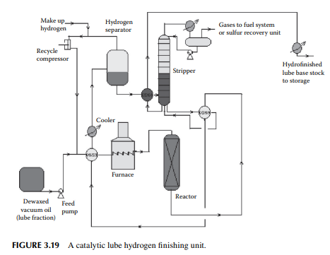
In the hydrofi nishing unit, catalytic hydrogenation is carried out in a fi xed bed reactor. A nickel–molybdenum or tungsten catalyst is used at a high partial pressure of hydrogen. Temperature and pressure are maintained at around 350°C and 50–80 kg/cm2, depending on the feedstock to be treated. The reactions involved over the catalyst are similar to those already discussed in Section 3.10 in the naphtha pretreatment unit. A typical hydrofi nishing unit for dewaxed oil is shown in Figure 3.19. It is to be noted that in a lube processing plant extraction, dewaxing and hydrofi nishing operations are carried in a chain for each distillate separately, e.g., IO cycle, HO cycle, and BS cycle. The capacity of the units in a chain must be designed to handle the maximum production of the desired vacuum distillates.
3.19 CATALYTIC PROCESSES FOR LUBE OIL BASE STOCK MANUFACTURE
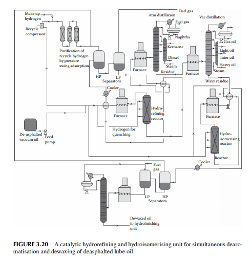
Selective dearomatisation and dewaxing of vacuum distillates using solvent extraction processes, as described in the previous sections, are being replaced by catalytic hydrogen processes. Hydrogenation of unsaturates and aromatics can be carried out selectively to adjust the viscosity and viscosity index, followed by catalytic dewaxing and hydrofi nishing processes. All these processes are carried out using different catalysts and different operating conditions in the presence of hydrogen. In these processes, neither any removal of any aromatic hydrocarbon molecule takes place nor any paraffi n wax is removed, but are converted to saturates and iso-paraffi ns as part of the lube oil components.
However, unwanted nitrogen, sulfur, oxygen, and metals are removed. A small amount of gases and lighter fractions may be formed as by-products. Hence, the yield of lube stocks per ton of feed distillate processed is much higher than that from solvent processes. In addition, the cost of recovery and loss of solvent and the huge cost in chilling and the refrigeration unit for dewaxing are avoided. The only disadvantage is that the by-products from solvent processes, such as aromatic rich extract (carbon black feedstock) and wax, are not produced in the catalytic processes and only the deasphalted oil can be handled. All these catalytic processes are divided into the following stages.
1. Deasphalting of residual feed by a solvent, e.g., propane, to avoid deactivation of the catalysts in the successive catalytic processes.
2. Hydrotreatment for removal of sulfur, nitrogen, oxygen, and metallic impurities from feedstock.
3. Hydrogenation to saturate aromatics in the dearomatising unit.
4. Hydroisomerisation of normal paraffi ns to iso-paraffi ns with or without selective mild hydrocracking of paraffi nic hydrocarbons as per requirement to reduce the pour point.
5. Hydrofi nishing reactions to adjust minor colour, sulfur, etc. A typical catalytic dearomatisation and dewaxing plant is shown in Figure 3.20
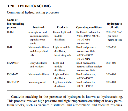
The reactions involved are dissociation of hydrocarbon molecules, hydrogenation of unsaturates, along with desulfurisation, denitrifi cation, deoxygenation, and demetallation, yielding good quality light and middle distillates, good lube distillates, fuel oil, etc. Various hydrocracking reactors and operating conditions are in use, depending on the type of feedstocks to be treated. For instance, VGO may be cracked in a fi xed bed reactor to yield light and middle distillates, whereas a residue hydrocracker is an ebulliated bed reactor yielding light distillates to heavy fuel oils. Since a large excess of hydrogen is used, the fi nal products have excellent qualities, i.e., low sulfur (almost free) kerosene and diesel oil, good quality aviation turbine fuel, good gasoline with high oxidation stability, good quality lube distillates with low sulfur, nitrogen, oxygen, and metallic impurities, and with a reduced coke yield. The table lists various well-known hydrocracking processes for various feedstocks. Though there are many hydrocracking processes, they differ mainly by the type of feedstock, product pattern, and catalyst, but the operating temperature varies from 400°C to 500°C and pressure above 10 MPa using in excess of
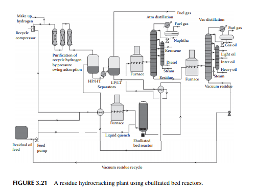
hydrogen circulation rate. The presence of nitrogen and metals in the feedstock are a major concern for the hydrocracking catalyst. Nitrogen yields ammonia, which destroys the acidic cracking sites of the catalyst, and metals deposited on the catalyst, poison the metal sites and also plug the porous catalyst. Hence, for such feedstocks, guard reactors are used to reduce the nitrogen and metal content of the feedstocks. Deasphalting is suggested for vacuum residues. Heavy aromatics present in the feedstock potential for yielding polynuclear aromatics (PNA) during hydrocracking reactions may need to be separated by vacuum distillation. It has been found that even with severe hydrocracking, PNA molecules cannot be destroyed which are found to be main ingredients of cokes. Most of the catalyst are made from transitional metals supported on alumina or silica. New catalysts are being prepared from molecular sieves. A typical fi xed bed hydrocracking unit is presented in Figure 3.21.
3.21 MILD HYDROCRACKING
The term “mild hydrocracking” implies hydrocracking at mild operating conditions. It is carried out mostly for producing middle distillates and fuel oils from vacuum distillates, catalytic dewaxing for lube base stock at a pressure below 10 MPa and at a temperature range varying from 350°C to 450°C. Since pressure is low compared to hydrocracking reactors, mild hydrocracking can be carried out in the traditional hydrotreatment reactors. Conversion of vacuum distillates may not exceed 50%.
3.22 HYDROGEN GENERATION
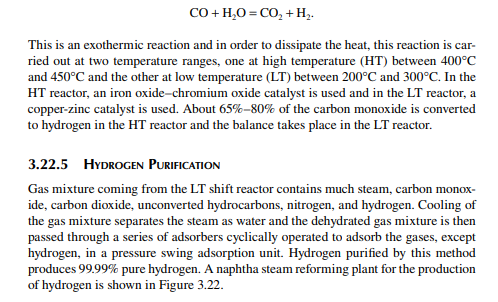
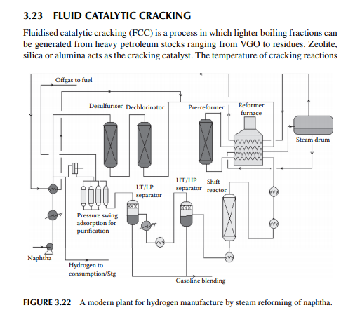
Hydrogen is essential for the various processing units in any modern refi nery, e.g., catalytic hydrogen-aided processes, such as desulfurisation, denitrogenation, demetallation, hydrogenation of aromatic and unsaturates, hydroisomerisation, and hydrocracking. Although hydrogen is obtained as the by-product from platforming reaction from naphtha, it is not suffi cient for all the hydrogen-aided processes. Hence, a separate hydrogen plant is essential to produce hydrogen of the required quantity and purity. Electrolysis of water produces purest hydrogen but at an enormous cost, hence commercial hydrogen is obtained from petroleum or coal. Depending on the type of feed used, commercial hydrogen processes are gas-, naphtha-, or coal-based plants. Coal-based hydrogen plants are the oldest and are mainly used for the production of water gas, producer gas, and synthesis gas. Gas-based plants use methane as the raw material, which reacts with steam in the presence of a catalyst to generate hydrogen. Naphtha-based plants use naphtha with a low aromatic content as the raw material, which generates hydrogen in the presence of steam and a catalyst. These processes were mainly developed for the production of synthesis gas (a mixture of hydrogen and nitrogen) required for ammonia production in fertiliser plants. Hydrogen yield is maximum from methane and it decreases with heavier feedstocks (C:H ratio increases). Since heavier petroleum produces coke, catalysts are quickly deactivated, therefore methane is preferred in most commercial processes. Alternatively, carbon monoxide from partial oxidation of heavy petroleum is used to produce hydrogen in the presence of steam. Hence, the selection of the routes of hydrogen manufacturing processes depends on the availability of the raw material, the purity and yield of the hydrogen, and the cost of separation of the by-products and their value. Catalyst are mainly nickel based, usually supported on alumina. Since sulfur, arsenic, and some other elements are found to be permanent poisons to this catalyst, raw material must be desulfurised and treated to remove the poisons before reforming. A steam reforming plant consists of a feed desulfurisation unit, a primary reformer, a secondary reformer, shift converters, a carbon dioxide absorber, a methanator, and a hydrogen purifi cation unit. The purpose of each unit is described in brief in the following subsections.
3.22.1 FEED DESULFURISATION
When the feed is methane or hydrocarbon gases, sulfur compounds are mainly present in the form of hydrogen sulfi de and mercaptans, hence the gases must be treated with amine solution to absorb the hydrogen sulfi de, followed by catalytic desulfurisation using a cobalt–molybdenum oxide catalyst in the presence of hydrogen. The reactions are similar to those described earlier in the catalytic hydrodesulfurisation processes. For naphtha or heavier petroleum feedstocks, the second step of desulfurisation is carried out.
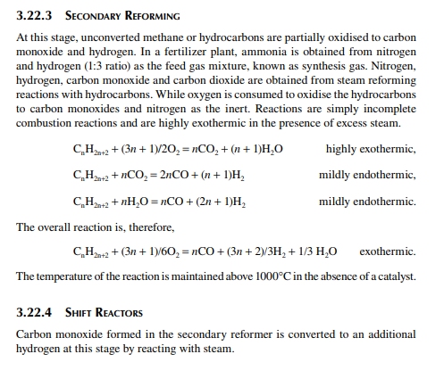
3.22.2 PRIMARY REFORMING
Desulfurised gas or naphtha preheated and mixed with steam is passed through a catalyst-packed (nickel) tube-still furnace where hydrogen is obtained due to the following reactions.
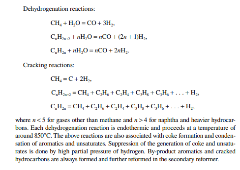
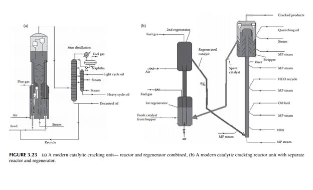
is in the range of 500°C–600°C. Feedstock rich in paraffi nic hydrocarbons are preferred, however cracking of naphthenes and aromatic rings also occurs. Simultaneous reactions, such as dehydrogenation of saturated hydrocarbons, cyclisation of straight chain compounds, isomerisation, decomposition of heavy hydrocarbons, and polycondensation of aromatics to form polynuclear aromatics (PNA), may occur during the reactions. Much coke is generated due to the breakdown of aromatic and heavier hydrocarbons and the formation and condensation of polynuclear aromatics (PNA), thereby reducing the activity of the catalyst. Most of the reactions are initiated by the acid sites of the catalyst that donates H+ ions. Fine catalyst powder is fl uidised in the tall tubular part (known as riser) of the reactor with the help of steam and light vaporisable hydrocarbons, like naphtha, which reduces the viscosity of the feed oil. Heavy feed oil is atomised by steam in the riser. Products are carried to the wider disengagement section of the reactor where products are disengaged from the catalyst through multistage cyclones. Hydrocarbon vapours from the reactor then enters a distillation column with side strippers for the recovery of various fractions. Spent catalyst laden with coke is transported to a fl uidised bed regenerator either below or at the side of the reactor where coke on the catalyst is burnt out to regenerate the catalyst from its temporary deactivation. The regenerated and hot catalyst is then returned to the riser reactor to continue the process of cracking. Air is used as the fl uidisation medium in the regenerator and the heat of combustion is used to maintain the reaction temperature. A small amount of coke (called equilibrium coke) is always retained on the surface and additional fresh catalyst must be maintained to compensate for the loss of activity. The organometallic hydrocarbons in the feed deposits metals on the surface of the catalyst, causing permanent deactivation of the catalyst. Usually, vanadium, nickel, and sodium are found in the feedstock and cause the deactivation. The presence of nitrogen in the feed also destroys the acid sites of the catalyst. Gases, gasoline, light cycle oil, heavy cycle oil, and residual oil contaminated with the catalyst are obtained from the distillation column. The light cycle oil goes to the diesel pool and the heavy cycle oil goes to the fuel oil pool. Residual oil goes to a catalyst decantation unit before it is recycled to the reactor. Decanted oil also acts as a quenching medium in the reactor. Gases and gasoline from the distillation column must be treated for sulfur removal separately. Because of the presence of olefi nic hydrocarbons in the gasoline, hydrogenation may be required to improve its oxidation stability. A typical FCC unit is shown in Figure 3.23. The success of an FCC unit depends on the quality of the feedstock. Paraffi nrich feedstock is good for cracking, whereas aromatic-rich feed produces more coke than light fractions. The carbon residue of the feed analysis is an indication of potential coke that could be generated during cracking. Coking is also desirable, to some extent, for heat generation in the regenerator for maintenance of the reaction temperature. There are also some disadvantages owing to the presence of cracked products, such as the high content of unsaturated hydrocarbons and aromatics, which give rise to poor burning quality and oxidation stability. Cracked gasoline has a high octane number but it has poor oxidation stability due to the presence of unsaturated hydrocarbons. It is also corrosive due to the presence of mercaptans originally present in the feed stocks. Blending of LCO in diesel may reduce the cetane number due to the increased amount of aromatics and branched hydrocarbons present in LCO.
3.24 BITUMEN BLOWING
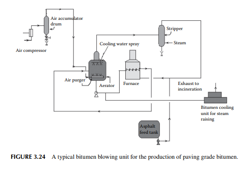
Bitumen is another name for asphalt. Raw asphalt from the deasphalting unit is blown with hot air in a furnace to adjust the softening point and penetration index for the production of paving grade bitumen. Depending on the surface temperature and the environment of application, the softening temperature and penetration index are adjusted by varying the air/feed ratio, temperature, and blowing time in the furnace. A typical bitumen blowing unit is shown in Figure 3.24. If the asphalt contains lower amounts of metals, these can be routed to the coking unit for production of metallurgical coke. It is a matter of fact that lube bearing crude oil yields asphalt of high metal content whereas non-lube bearing crudes yield asphalts with low metallic contents. As a result, asphalts from lube bearing crude is suitable for the production of bitumen, whereas asphalts and SRs and even heavy vacuum distillates from nonlube bearing crude are suitable for coke production.
3.25 VIS-BREAKING
Vis-breaking or viscosity breaking is a mild thermal cracking unit that produces low viscosity fuel oil from a high viscosity oil stock. In this method, the feedstock is usually a mixture of high vacuum distillates and residues, even asphalt, heated in a furnace at a cracking temperature (slightly above 400°C) at a pressure above atmosphere for a short time and quickly quenched and fl ashed in a plated column. Suffi cient steam is used to separate the cracked light hydrocarbons. Products include gases, gasoline (VB gasoline or naphtha), gas oil (VB gas oil), and low viscous fuel oil or furnace oil as the major product. A typical vis-breaking unit is shown in Figure 3.25. As shown in the fi gure, heavy viscous vacuum oils, residue from the
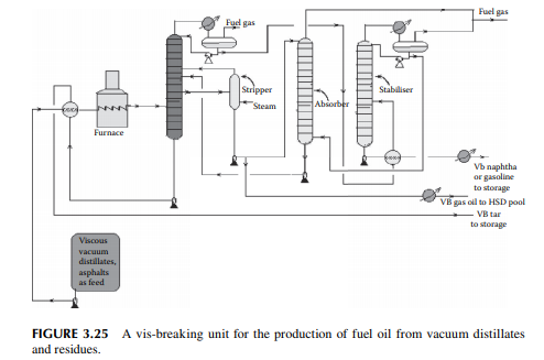
vacuum distillation unit, and asphalt from a propane deasphalting unit are the feedstocks, which are preheated by hot products followed by heating in a tube-still furnace and then fl ashed in a distillation column. Top vapours enter a stabiliser column to separate the gases and VB naphtha components. Gases are further scrubbed in an absorber tower by VB gas oil from the main distillation column. Gases leaving the absorber tower are used as fuel gas and the rich gas oil stream containing scrubbed hydrocarbons from the gases is recycled back to the main fractionator column. The bottom of the main fractionator column is the VB tar (black oil) which is the cheapest and major fuel for the industrial furnaces. The by-products are VB gas oil and VB naphtha. VB gas oil is mixed with the straight run, vacuum, light cycle gas oils, etc., for HSD as the fi nal product. VB naphtha has medium octane number and is blended with high octane components like cat cracked gasoline and reformate. Since the products from this unit contain much mercaptans and unsaturated hydrocarbons, meroxing or desulfurising is essential. Catalytic hydrodesulfurisation may be benefi cial as far as the removal of sulfur and olefi ns/di-olifi ns is concerned, but at the cost of an octane number.
3.26 COKING
The coking unit of a refi nery yields petroleum coke, which is heavily condensed hydrocarbon with more than 90% carbon. This high carbon stock is used in the metallurgical and graphite industries for extraction of metals from ores and also as a clean fuel. As already mentioned, non-lube bearing crude oil yields large residual masses and asphalts with minimum metal and sulfur content, which are suitable for the production of petroleum coke. The coking unit uses various methods depending
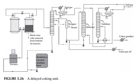
on the properties required by the users. Delayed coking and fl uid coking plants are commonly employed in refi neries. In the delayed coking unit, feedstock is heated in a furnace to a temperature of around 480°C–500°C at high velocity to before sending to a coking drum where a long residence time allows the coking reactions to go to completion, thereby maximising coke formation. Once the coke drum is fi lled, another empty coking drum is pressed into service, the fi lled drum is isolated and coke is cut off by a high velocity water jet. In any such unit, a minimum of two coking drums or chambers are required, however more drums or high volume chambers may be used. A typical delayed coking unit is shown in Figure 3.26. In the fl uid coking method, a fl uidised bed of coke is used by atomising feedstock with steam and the high temperature is maintained by partially burning the coke particles in a fl uidised bed burner.
QUESTIONS
1. Why is desalting of crude necessary?
2. What is the operating procedure for an electric desalter?
3. Present a fl owsheet diagram for a crude distillation unit and its accessories, indicating the equipment involved and explain their functions.
4. Distinguish between sour and sweet crudes.
5. What is a Doctor’s test?
6. What are the various parameters that distinguish different crudes?
7. What are the differences between the extractive and sweetening mercaptan oxidation methods?
8. Would you suggest merox treatment while catalytic hydrogenation is also available?
9. Why is pretreatment of naphtha required before plat-forming? Also, mention the predominant reactions involved in catalytic reforming
10. Present a fl owsheet diagram of a naphtha reforming plant, mentioning the necessity of each piece of equipment present in the fl ow sheet.
11. Why is debutanisation of the reformate required?
12. What are the methods for manufacturing benzene-free gasoline? 13. What are the various components of gasoline?
14. Distinguish between a thermal cracking unit and a catalytic cracking unit.
15. How do the qualities of gasoline from an FCC and reformer differ?
16. Discuss the qualities of middle distillates obtained from an FCC unit.
17. What are the effects of nickel, vanadium, and sodium present in the feedstock on an FCC unit? What are the necessary precautions required in an FCC unit in case feed contains all these metals?
18. Defi ne the terms spent catalyst, regenerated catalyst, and equilibrium coke.
19. What are the functions of a waste heat boiler in an FCC unit?
20. How is petroleum coke manufactured?
21. What are the advantages and disadvantages of a hydrocracking unit?
22. What is mild hydrocracking?