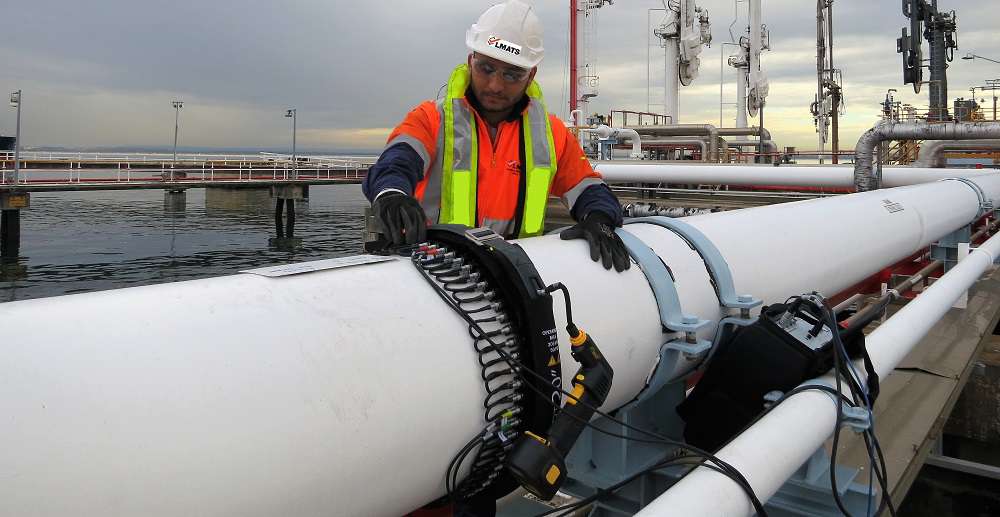
Guided wave ultrasonic testing detects corrosion damage and other defects over long 33 ft. – 165 ft. distances in piping. A special tool (transducer ring) is clamped around the pipe and transmits guided waves in both directions along the pipe. Reflected signals from defects and pipe features such as welds are received by the transducer ring and sent to the main unit.

IRISNDT APPLIES GWT
○ To inspect sleeved road crossings
○ To detect riser soil to air interface losses
○ To detect corrosion under insulation
○ To detect pipe rack support losses in-situ
○ To inspect buried or insulated lines
○ Difficult to access locations
ADVANTAGES
○ Inspects difficult to access components without extensive excavation or insulation removal
○ Portable, battery powered equipment
○ Sophisticated software routines help identify and classify pipe signals
○ Rigorous operator training and certification with individual electronic keys which activate the system and track its use by each operator
○ Embedded reporting software allows the operator to analyze the results and produce a report on the spot
LIMITATIONS
Under good conditions, GWT inspects over 330 ft. in uncoated, straight, gas-filled pipe. Most pipes will have an effective range of between 16 ft – 165 ft. The effective range for guided wave inspection can be inhibited by:
Coatings: bitumen wrap and similar heavy coatings cause high attenuation
○ Pipe condition: corroded line scatters UT signals and reduces range
○ Features such as welds: each weld typically reflects 20% of the signal. Without other limiting factors, six welds set the maximum span
○ Bends and ‘T’ junctions: these features distort the signal, one generally cannot test beyond a bend
○ Pipe contents: high viscosity liquids or waxy deposits attenuate the signal
○ Special soil conditions can cause additional attenuation and are usually associated with wrapped pipe
○ Complementary inspection methods are needed to map out and size flaws found with GWT; typically UT and RT are used
ON SITE REQUIREMENTS
○ Access to the pipe and removal of about 3.3 ft. length of insulation at each test point
○ Surface preparation is usually limited to scraping off loose paint and scale
○ At least 3 inch of clearance between pipes to fit the tool
○ Pipe surface temperature must generally be below 160 °F although high temperature 644 °F rings are available
GWT FUNDAMENTALS
Ultrasonic signals are swept over a full frequency range, in both directions from the GWT tool, in a single shot. In addition to faster, more efficient data acquisition, having all the data in a single file makes analysis faster and more certain. Sophisticated processing and analysis software allows trained operators to interpret these signals and report their findings. Special, wide frequency probes are available for cases such as buried pipe where attenuation is too high over the standard frequency range.
Enhanced Focusing Capability (EFC) rings (pipe 4 inch and above) improve defect characterization and provides colour coded C-scan type maps of the pipe. In effect, the EFC processing focuses on all reflectors over the entire range of the shot. This improves sensitivity as well as making the guided wave data more understandable to the end user.