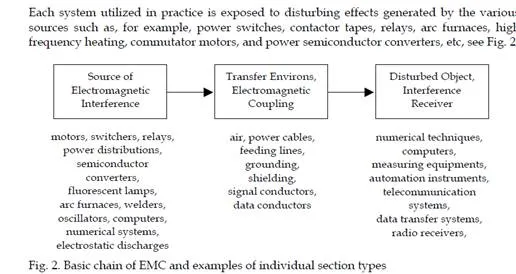
Equipment disturbances and errors have become more serious as a consequence of the growth of the electronic circuit complexity. According to new technical legislation and also economic consequences, the electromagnetic compatibility (EMC) concept of all products must be strictly observed (Montrose & Nakauchi, 2004). It must start with the specification of the equipment performance and end with the equipment installation procedures. The importance of the electromagnetic compatibility (EMC) of all electrical products has grown rapidly during the last decade. The environment is increasingly polluted with electromagnetic energy. The interference output into the surroundings is doubled every three years, and covers a large frequency range.
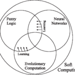
EMC couplings
The EMC concept is defined as competence of functional coexistence of electrical and also biological devices or systems at the same time and in such a way that even though they are located in the common electromagnetic environs, there is no relevant influencing factor of their normal functionality (Vaculíková & Vaculík, 1998). Devices can but don’t need to have the mutual dependence. On the one hand the systems must be robust against the other systems influences, but on the other hand they must not affect adversely the normal functionality of other devices (Fig. 1). On one side, interferences are deliberately or involuntarily produced. The place of their origin is called interference source. On the other side, devices can be hindered in their function by such interferences. Those objects are called interference objects.

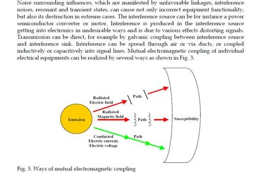
From the viewpoint of the theoretical analysis it is evident that the radiated energy transfer between individual investigated equipments is done by the following ways: inductive coupling, capacitive coupling, galvanic coupling, electromagnetic coupling.
Inductive coupling
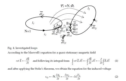
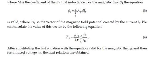
Inductive coupling is typical for two and more galvanically separated electric loops at the moment when the smaller one is driven by a time variable current creating the corresponding time-variable magnetic field (Kůs, 2002). In such case their mutual intercircuit effect is expressed as a function of the slope of the current increase or decrease, circuit environmental magnetic property as well as circuit geometric dimensions. To predict the intercircuit inductive coupling, our focus will be on two electric loops l1 and l2
with currents i1 and i2. We will try to determine the effect of loop l1 on loop l2 (Fig. 4).
Capacitive coupling
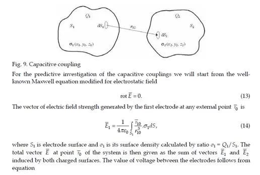
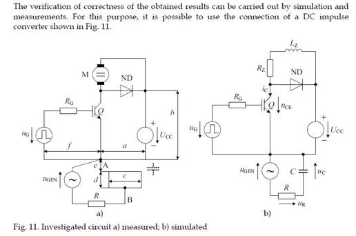
![]() The capacitive coupling is typical for galvanically separated circuit nodes among which the mutual influence is represented by electric field strength E . Its distribution is given by the potential at the particular nodes, geometry of the system and dielectric properties of materials and media involved (Fig. 9).
The capacitive coupling is typical for galvanically separated circuit nodes among which the mutual influence is represented by electric field strength E . Its distribution is given by the potential at the particular nodes, geometry of the system and dielectric properties of materials and media involved (Fig. 9).
Solution for the low frequencies and concentrated parameters
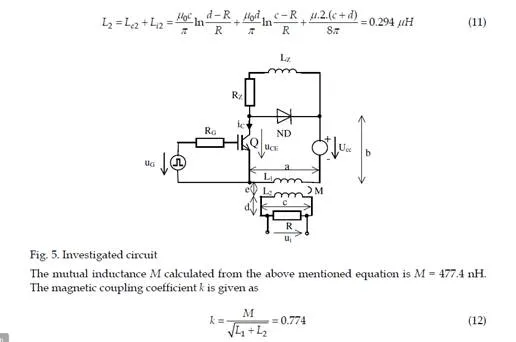
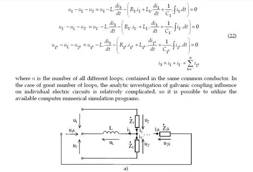
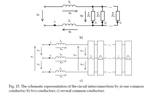
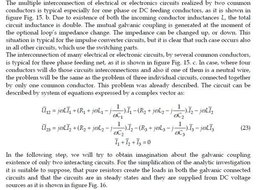
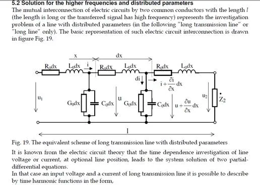
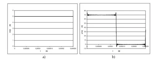
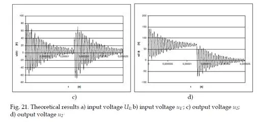
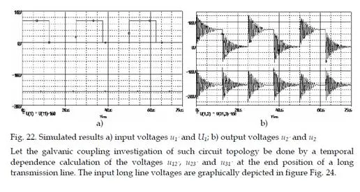
Minimum two or more electric circuits, which are mutually galvanically interconnected by one common conductor with its length l, represent a type of galvanic coupling. Due to low frequency operation it is possible to define the common conductor electrical parameters by concentrated parameters of its resistance R and inductance L. If we suppose in the next step, that the conductor will be made of copper, so the voltage drop on its resistance R will be much smaller in comparison with the voltage drop across its inductance L, which is caused by the time depending change of current. So, for the simplified analysis of the problem the conductor resistance will be neglected in the following. The schematic representation of the described problem is shown in the following figure Fig. 15. The mathematical description of the situation in the investigated circuit (Fig. 15. a) is then given by the next system of integral-differential equations (if the load created by serial connection of R1, L1 and C1 components is supposed):
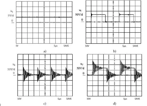
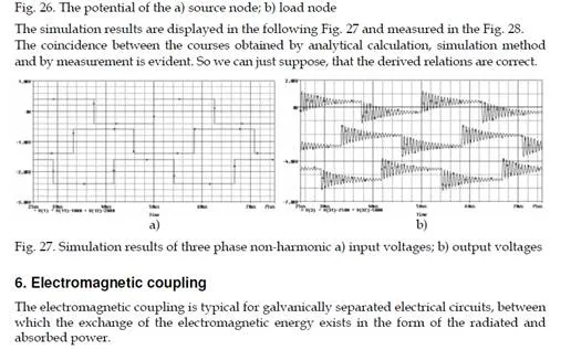
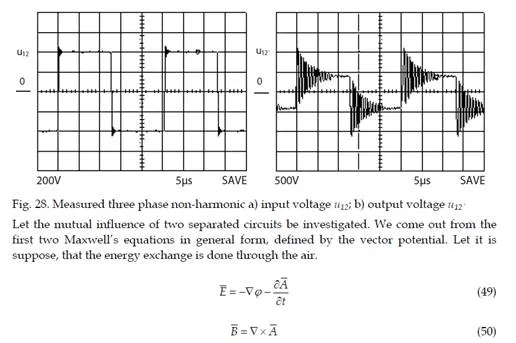
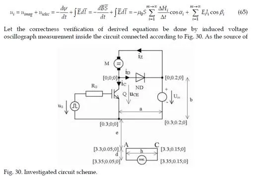
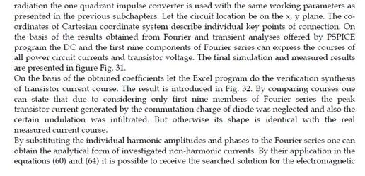
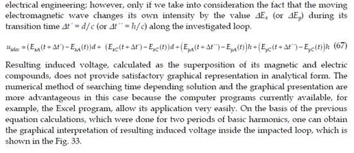
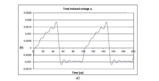
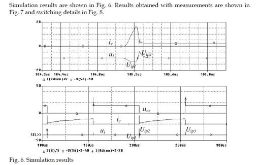
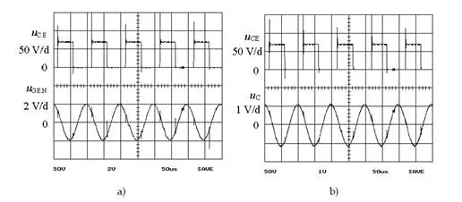
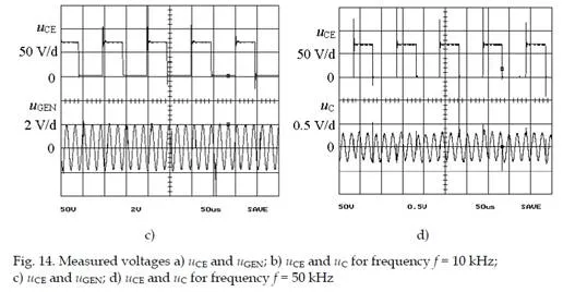
By comparing the simulated and measured results one can find out that positive amplitudes reach approximately the same values 1.8 mV and similarly the negative amplitudes have the values 1 mV. The existing ripple and the absence of short positive voltage impulse with the amplitude 2.5 mV inside the induced voltage course obtained by simulation is caused by considering only the first nine components of Fourier series. Generally it is possible to say that there exists a relatively great coincidence between the simulated and measured results. Thus the correctness of derived equations is confirmed as well as the fact that if higher number of Fourier series components are used the better coincidence of both type results will be obtained. It means that during the electromagnetic coupling investigation, as one part of general EMC investigation, it is necessary to reconsider the compromise between the number of Fourier series components and the required calculation precision.The above-mentioned simulated and measured results are sufficiently identical with the theoretical results and so they confirm the correctness of derived equations. Such a way they can be used for predictive stating of EMC quality of individual new electrotechnical products (Williams, 2001).Based on the performed analysis also we can find out that the intensity of electromagnetic coupling is directly proportional to the amount and the time change slope of circuit current, which is radiating the electromagnetic energy. In the same way electromagnetic coupling intensity depends on the length of this circuit. It is also directly proportional to the surface and the length values of disturbed circuit. It is indirectly proportional to the distance between the interference source and the disturbed circuits, to the reflection coefficient and to the permeability and permittivity values of space between the both circuits.
Conclusion
The performed analysis enables constructers to improve the EMC parameters of the newly constructed devices not only by expensive testing measurements, but also in advance, by the theoretical analysis and simulation. They can state its supposed and required properties by a predictive method based upon the results introduced in this chapter (Kováčová et al., 2006). The improving of EMC will thus be more comfortable, cheaper, easier and quicker.