Based on the type of work transfer system that is used in the assembly system:
· Continuous transfer system
· Synchronous transfer system
· Asynchronous transfer system
· Stationary base part system
The first three types involve the same methods of work part transport described in automated flow line. In the stationary base part system, the base part to which the other components are added is placed in a fixed location, where it remains during the assembly work.
Based on physical configuration:
· Dial-type assembly machine
· In-line assembly machine
· Carousel assembly system
· Single-station assembly machine
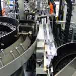
The dial-type machine, the base part are indexed around a circular table or dial. The workstations are stationary and usually located around the outside periphery of the dial. The parts ride on the rotating table and arc registered or positioned, in turn, at each station a new component is added to base part. This type of equipment is often referred to as an indexing machine or dial index machine and the configuration is shown in Figure 1 and example of six station rotary shown in figure 2.

Figure 1 Rotary configuration

Figure 2 Example of 6 station rotary configuration for assembly
In-line type configuration
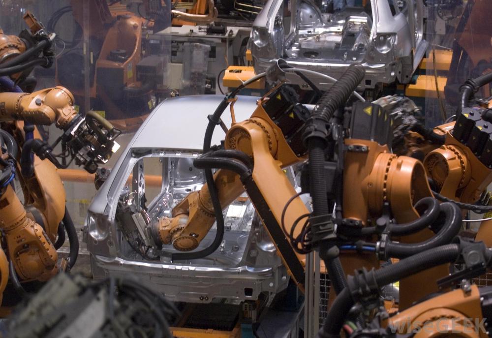
The in-line configuration assembly system consists of a sequence of workstations in a more-or-less straight-line arrangement as shown in figure 3. An example of an in-line transfer machine used for metal-cutting operations is illustrated in Figure 4. The in-line assembly machine consists of a series of automatic workstations located along an in-line transfer system. It is the automated version of the manual assembly line. Continuous, synchronous, or asynchronous transfer systems can be used with the in-line configuration.

Figure 3 In-line configuration for assembly system
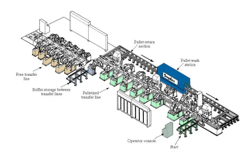
Figure 4 Example of 20 stations In-line configuration
Segmented In-line type
The segmented in-line configuration consists of two or more straight-line arrangement which are usually perpendicular to each other with L-Shaped or U-shaped or Rectangular shaped as shown in figure 5-7. The flow of work can take a few 90° turns, either for workpieces reorientation, factory layout limitations, or other reasons, and still qualify as a straight-line configuration.

Figure 5 L-shaped configuration

Figure 6 U-shaped configuration
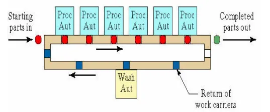
Figure 7 Rectangular-shaped configuration
Carousel assembly system
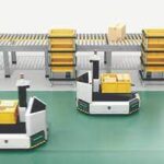
It represents a hybrid between the circular flow of work provided by the dial assembly machine and straight work flow of the in-line. It is as shown in the figure 8
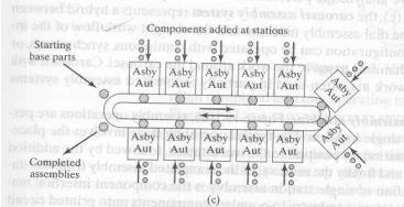
Figure 8 configuration of a carrousel assembly system
Single- station assembly machine
In the single-station assembly machine, the assembly operations are performed at a single location (stationary base part system) as shown in figure 9. The typical operation involves the placement of the base part at the workstation where various components are added to the base. The components are delivered to the station by feeding mechanisms, and one or more work heads perform the various assembly and fastening operations.
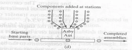
Figure 9 Single-station assembly machine