Unless you work for a company designing custom “one-off” products you often find yourself creating a finite element model with similar aspects to models you have worked on previously. In my own distant past I worked for companies that produced tables of products which shared many common attributes in form, function and methods that I used to analyze them. Granted, this was back in the days before we had cool things like parametric CAD connections and user friendly finite element codes but we also had no concept that the future also held reality TV, flavored water, and Justin Bieber.
Our finite element models were often painstakingly generated by hand because even if we had a CAD model we had no good way to get it into the FE code. Things slowly improved with the advent of CAD model readers but in most cases these were one-way trips for the geometry and still required a significant amount of local modification before we could get a finite element mesh generated. We would 1) import geometry for model “A” into a preprocessor, 2) clean it up, 3) mesh it, 4) apply boundary conditions and 5) solve. If we were lucky the finite element analysis results met specifications. If not we had to at best modify the geometry locally and repeat steps 3-5. At worst we had to go back to the CAD model and begin the entire process all over again. Similar products had to follow the same steps from start to finish as there was no easy way to substitute a new geometry into an existing model.
We survived and some may argue that we have a better appreciation of the current capabilities as a result. No doubt the slide rule generation felt the same way about calculators. The next generation of engineers will likely have 3D virtual reality models like Tony Stark in the recent “Iron Man” movies. I hope I’m around to witness the next big leap in engineering design tools. As for the next reality TV juggernaut? I can skip that.
 |
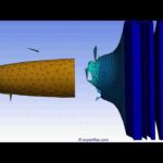
Now, before we get too far ahead of ourselves, let’s consider what we (represented by the guy with the spear) currently have available. In recent years, there has been a considerable amount of effort made by the finite element tool developers to link the CAD geometry to the finite element geometry. Geometry connections are more robust (meaning fewer import problems and less repair required) and include other facets of the CAD model. Most CAD tools at present are feature based, using sketches and modeling operations to create geometry. The sketch geometry and the 3D operations are controlled by modifying the parameters (dimensions) that define them. A “bi-directional” CAD connection allows you to share both the geometry and the driving parameters with the finite element program. However, not all finite element programs are created equal and if you are using a tool that does not have this capability you are giving up your spear and making due with a club (see the figure above).
With geometry and parameters available we can make models that require little user interaction to update. Material assignments, connections, mesh controls, boundary conditions, and scoped results are assigned to geometry facets (tags) and the tags stay the same when the model is modified parametrically. If the tags do not change the finite element tool knows where to apply the attributes to the new geometry. This lends itself nicely to automation such as a “what if?” study or a more detailed optimization approach like a Design of Experiments analysis.
But wait, there’s more! Some connection products can import groups of geometry (Named Selections) defined at the CAD level. These geometry groups can be used to define all the finite element model attributes eliminating the need for any manual picking of the entities.
Consider the following example. You need to analyze a family of products with the following characteristics:
● The designs are similar in the way that you model them but come from different CAD files.
● There is no guarantee that the geometry tags will be the same for each model.
● The parameters you will modify are the same for each design but may not have the same names in the CAD models.
● Your product development schedule is tight and you need to get this done quickly and efficiently.
The options available to you are:
1. Lapse into despair
2. Model each design separately, increasing the potential for human error, and spending lots of extra hours at the office while the important facets of your life take a back seat.
3. Plan ahead:
● Develop a common nomenclature for the parameters and geometry regions at the CAD level.
● Attach the first CAD geometry in your finite element tool.
● Set up your connections, mesh settings, boundary conditions and result regions using the Named Selections from the CAD geometry.
● Identify result parameters for your “what-if” study (mass, reaction force, displacement, strain and stress).
● Create a table of potential design configurations using the input parameters.
● Kick off a batch run of your design points and track the response of the output quantities.
● Present the solution to your colleagues and bask in their admiration and astonishment at how quickly you accomplished this.
Clearly option #3 is the preferred method, and unbeknownst to your colleagues, you still have another major trick up your sleeve. Developing that common nomenclature across the entire family of CAD models will now allow you to use your original FE model as a template for the remaining designs. You simply replace the original CAD model with the next design and all the initial work of setting up the model and the parameter study will be applied to the new model. The remaining members of the design family can be analyzed with two simple steps: update the model and solve!
 |