


Posted inMaterial Science
Dislocations and Strengthening Mechanisms
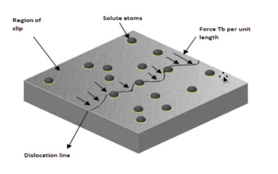
Basic Concept of dislocation Dislocations can be edge dislocations, screw dislocations and exist in combination of the two. Their motion (slip) occurs by sequential bond breaking and bond reforming . The number of dislocations per unit volume is the dislocation density, in a plane they are measured per unit area. Characteristics of Dislocations There is strain around a dislocation which influences how they interact with other dislocations, impurities, etc. There is compression near the extra plane (higher atomic density) and tension following the dislocation line. Dislocations interact among themselves. When they are in the same plane, they repel if they…