Liquid-Penetration test

Liquid-Penetration test

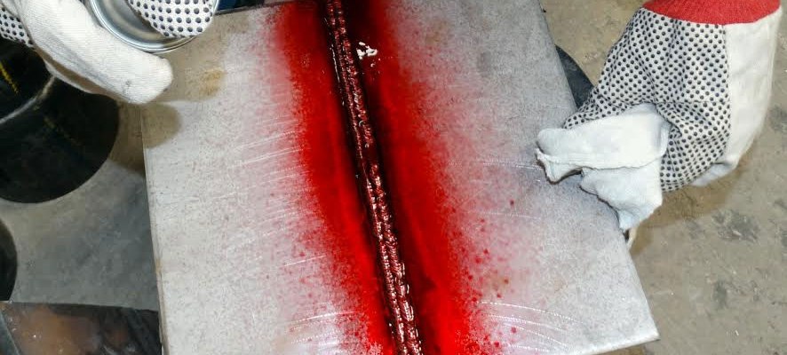
This test is employed for detection of small defects which are very small to detect with the naked eye. This test is used to detect surface cracks or flaws in non-ferrous metals. This test employs a visible colour contrast dye penetrant technique for the detection of open surface flaws in metallic and non-metallic objects. The penetrants are applied by spraying over the surface of material to be inspected. The excess penetrant is then washed or cleaned. Absorbent powder is then applied to absorb the penetrants in the cracks, voids which reveals the flaws. This test reveals flaws such as shrinkage cracks, porosity, fatigue cracks, grinding cracks, forging cracks, seams, heat treatment cracks and leaks etc., on castings, weldings, machined parts, cutting tools, pipes and tubes. If the fluorescent penetrant is used, the developed surface must be examined under ultra violet light to see the presence of defects. This technique is used for non-porous and non- absorbent materials. Care may be taken to clean the surface so that it is free from dust, scale, etc. to have better results. Penetrants are highly toxic and flammable and hence proper precautions should be taken both during use and…
Strain Hardening

Strain Hardening

Phenomenon  where  ductile  metals  become  stronger  and  harder  when  they  are  deformed plastically is called strain hardening or work hardening. Increasing temperature lowers the rate of strain hardening. Hence materials are strain hardened at low temperatures, thus also called cold working. During plastic deformation, dislocation density increases. And thus their interaction with each other resulting in increase in yield stress. Strain hardening (work hardening) is the reason for the elastic recovery. The reason for strain hardening is that the dislocation density increases with plastic deformation (cold work) due to multiplication. The average distance between dislocations then decreases and dislocations start blocking the motion of each one
Solid-Solution Strengthening

Solid-Solution Strengthening

Adding  another  element  that  goes  into  interstitial  or  substitutional  positions  in  a  solution increases strength. The impurity atoms cause lattice strain (Figs. 7.17 and 7.18) which can "anchor" dislocations. This occurs when the strain caused by the alloying element compensates that of the dislocation, thus achieving a state of low potential energy. It costs strain energy for the dislocation to move away from this state (which is like a potential well). The scarcity of energy at low temperatures is why slip is hindered. Pure metals are almost always softer than their alloys.
Strengthening by Grain Size Reduction

Strengthening by Grain Size Reduction

This is based on the fact that it is difficult for a dislocation to pass into another grain, especially if it is very misaligned. Atomic disorder at the boundary causes discontinuity in slip planes. For high-angle grain boundaries, stress at end of slip plane may trigger new dislocations in adjacent grains. Small angle grain boundaries are not effective in blocking dislocations. The finer the grains, the larger the area of grain boundaries that impedes dislocation motion. Grain-size reduction usually improves toughness as well. Grain size can be controlled by the rate of solidification and by plastic deformation.
Mechanisms of Strengthening in Metals

Mechanisms of Strengthening in Metals

General principles. Ability to deform plastically depends on ability of dislocations to move. Strengthening consists in hindering dislocation motion. We discuss the methods of grain-size reduction, solid-solution alloying and strain hardening. These are for single phase metals. We discuss others when treating alloys. Ordinarily, strengthening reduces ductility.
Plastic Deformation

Plastic Deformation

Slip directions vary from crystal to crystal. When plastic deformation occurs in a grain, it will be constrained by its neighbors, which may be less favorably oriented. As a result, polycrystalline metals are stronger than single crystals (the exception is the perfect single crystal, as in whiskers.)
Dislocations and Strengthening Mechanisms

Dislocations and Strengthening Mechanisms

Basic Concept of dislocation Dislocations can be edge dislocations, screw dislocations and exist in combination of the two. Their motion (slip) occurs by sequential bond breaking and bond reforming . The number of dislocations per unit volume is the dislocation density, in a plane they are measured per unit area. Characteristics of Dislocations There is strain around a dislocation which influences how they interact with other dislocations, impurities, etc. There is compression near the extra plane (higher atomic density) and tension following the dislocation line. Dislocations interact among themselves. When they are in the same plane, they repel if they…
Stress and Temperature Effects

Stress and Temperature Effects

Both temperature and the level of the applied stress influence the creep characteristics. The results of creep rupture tests are most commonly presented as the logarithm of stress versus   the   logarithm   of   rupture   lifetime.   Creep   becomes   more   pronounced   at   higher temperatures. There is essentially no creep at temperatures below 40% of the melting point Creep increases at higher applied stresses. The behavior can be characterized by the following expression, where K, n and Qc are constants for a given material:                                        dε/dt = K σn exp(-Qc/RT)
Creep

Creep

Creep is the time-varying plastic deformation of a material stressed at high temperatures. Examples: turbine blades, steam generators. Keys are the time dependence of the strain and the high temperature. The Creep Curve Creep in metals is defined as time dependent plastic deformation at constant stress (or load) and temperature. The form of a typical creep curve of strain versus time is in Figure. The slope of this curve is the creep rate dε/dt. The curve may show the instantaneous elastic and plastic strain that occurs as the load is applied, followed by the plastic strain which occurs over time. Three stages to the creep curve may be identified:…
Crack Initiation and Propagation

Crack Initiation and Propagation

Stages is fatigue failure: I. crack initiation at high stress points (stress raisers) II. propagation (incremental in each cycle) III. final failure by fracture Stage I - propagation •   slow •   along crystallographic planes of high shear stress •   flat and featureless fatigue surface Stage II - propagation Crack…