Strain Hardening

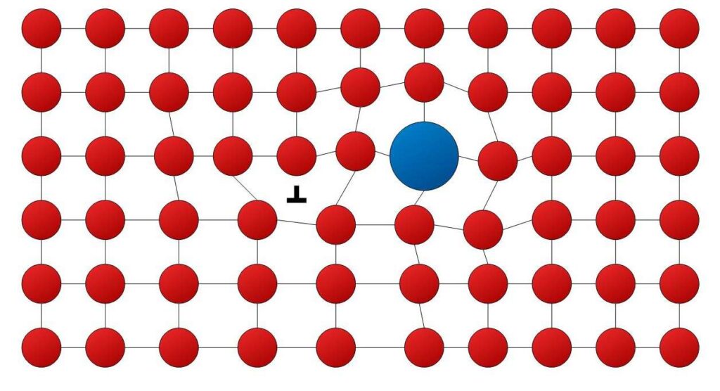
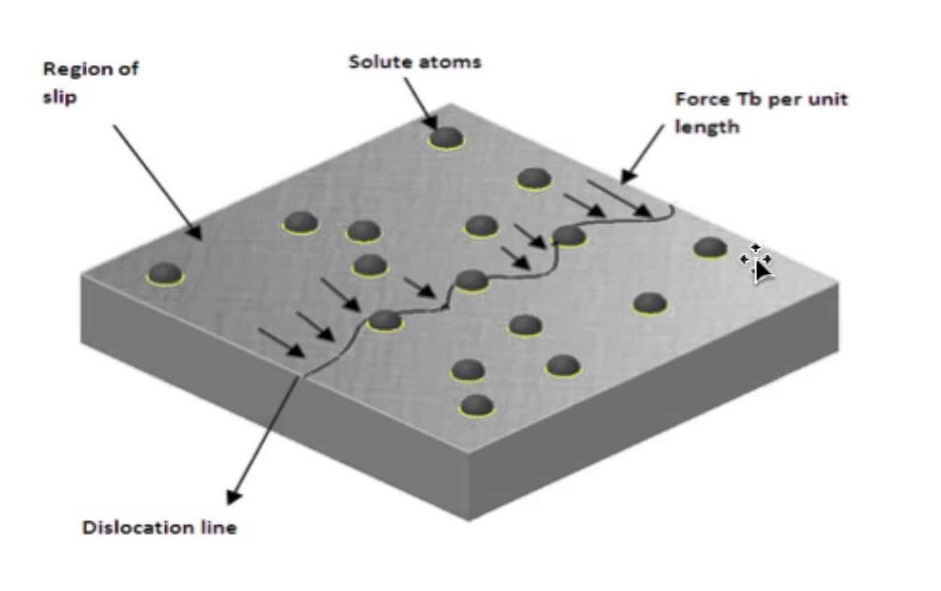
Phenomenon  where  ductile  metals  become  stronger  and  harder  when  they  are  deformed plastically is called strain hardening or work hardening. Increasing temperature lowers the rate of strain hardening. Hence materials are strain hardened at low temperatures, thus also called cold working. During plastic deformation, dislocation density increases. And thus their interaction with each other resulting in increase in yield stress. Strain hardening (work hardening) is the reason for the elastic recovery. The reason for strain hardening is that the dislocation density increases with plastic deformation (cold work) due to multiplication. The average distance between dislocations then decreases and dislocations start blocking the motion of each one

Read More

Solid-Solution Strengthening

Adding  another  element  that  goes  into  interstitial  or  substitutional  positions  in  a  solution increases strength. The impurity atoms cause lattice strain (Figs. 7.17 and 7.18) which can “anchor” dislocations. This occurs when the strain caused by the alloying element compensates that of the dislocation, thus achieving a state of low potential energy. It costs strain energy for the dislocation to move away from this state (which is like a potential well). The scarcity of energy at low temperatures is why slip is hindered. Pure metals are almost always softer than their alloys.

Read More

Strengthening by Grain Size Reduction

This is based on the fact that it is difficult for a dislocation to pass into another grain, especially if it is very misaligned. Atomic disorder at the boundary causes discontinuity in slip planes. For high-angle grain boundaries, stress at end of slip plane may trigger new dislocations in adjacent grains. Small angle grain boundaries are not effective in blocking dislocations. The finer the grains, the larger the area of grain boundaries that impedes dislocation motion. Grain-size reduction usually improves toughness as well. Grain size can be controlled by the rate of solidification and by plastic deformation.

Read More

Mechanisms of Strengthening in Metals

General principles. Ability to deform plastically depends on ability of dislocations to move. Strengthening consists in hindering dislocation motion. We discuss the methods of grain-size reduction, solid-solution alloying and strain hardening. These are for single phase metals. We discuss others when treating alloys. Ordinarily, strengthening reduces ductility.

Read More

Plastic Deformation

Slip directions vary from crystal to crystal. When plastic deformation occurs in a grain, it will be constrained by its neighbors, which may be less favorably oriented. As a result, polycrystalline metals are stronger than single crystals (the exception is the perfect single crystal, as in whiskers.)

Read More

Dislocations and Strengthening Mechanisms

Basic Concept of dislocation Dislocations can be edge dislocations, screw dislocations and exist in combination of the two. Their motion (slip) occurs by sequential bond breaking and bond reforming . The number of dislocations per unit volume is the dislocation density, in a plane they are measured per unit area. Characteristics of Dislocations There is strain around a dislocation which influences how they interact with other dislocations, impurities, etc. There is compression near the extra plane (higher atomic density) and tension following the dislocation line. Dislocations interact among themselves. When they are in the same plane, they repel if they have the same sign and annihilate if they have opposite signs (leaving behind a perfect crystal). In general, when dislocations are close and their strain fields add to a larger value, they repel, because being close increases the potential energy (it takes energy to strain a region of the material). The number of dislocations increases dramatically during plastic deformation. Dislocations spawn from existing dislocations, and from defects, grain boundaries and surface irregularities.

Read More

Stress and Temperature Effects

Both temperature and the level of the applied stress influence the creep characteristics. The results of creep rupture tests are most commonly presented as the logarithm of stress versus   the   logarithm   of   rupture   lifetime.   Creep   becomes   more   pronounced   at   higher temperatures. There is essentially no creep at temperatures below 40% of the melting point Creep increases at higher applied stresses. The behavior can be characterized by the following expression, where K, n and Qc are constants for a given material:                                        dε/dt = K σn exp(-Qc/RT)

Read More

Creep

Creep is the time-varying plastic deformation of a material stressed at high temperatures. Examples: turbine blades, steam generators. Keys are the time dependence of the strain and the high temperature. The Creep Curve Creep in metals is defined as time dependent plastic deformation at constant stress (or load) and temperature. The form of a typical creep curve of strain versus time is in Figure. The slope of this curve is the creep rate dε/dt. The curve may show the instantaneous elastic and plastic strain that occurs as the load is applied, followed by the plastic strain which occurs over time. Three stages to the creep curve may be identified: Primary creep: in which the creep resistance increases with strain leading to a decreasing creep strain rate. Secondary (Steady State) creep: in which there is a balance between work hardening and recovery processes, leading to a minimum constant creep rate. Tertiary creep: in which there is an accelerating creep rate due to the accumulating damage, which leads to creep rupture, and which may only be seen at high temperatures and stresses and in constant load machines. The  minimum  secondary  creep  rate  is  of  most  interest  to  design  engineers,  since  failure avoidance  is  required  and  in  this  region  some  predictability  is  possible.  In  the  USA  two Standards are commonly used: (i) The stress to produce a creep rate of 0.0001% per hour (1% in 10,000 hours). (ii) The stress to produce a creep rate of 0.00001% per hour (1% in 100,000 hours or approximately 11.5 years). The first requirement would be typical of that for gas turbine blades, while the second for steam turbines. Constant load machines simulate real engineering situations more accurately, but as the specimen extends its cross section area reduces, leading to a rising stress. Machines designed to reduce the load to compensate for the reduced area and maintain constant stress may produce an extended steady state region.

Read More

Crack Initiation and Propagation

Stages is fatigue failure: I. crack initiation at high stress points (stress raisers) II. propagation (incremental in each cycle) III. final failure by fracture Stage I – propagation •   slow •   along crystallographic planes of high shear stress •   flat and featureless fatigue surface Stage II – propagation Crack propagates by repetitive plastic blunting and sharpening of the crack tip.

Read More

Fatigue

Fatigue is the catastrophic failure due to dynamic (fluctuating) stresses. It can happen in bridges, airplanes, machine components, etc. The characteristics are: • long period of cyclic strain •   the most usual (90%) of metallic failures (happens also in ceramics and polymers) •   is brittle-like even in ductile metals, with little plastic deformation •   it occurs in stages involving the initiation andpropagation of cracks. Cyclic Stresses These are characterized by maximum, minimum and mean stress, the stress amplitude, and the stress ratio.

Read More