ELECTRICAL BASED PROCESSES

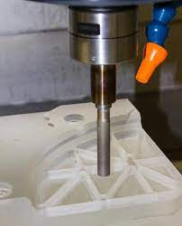
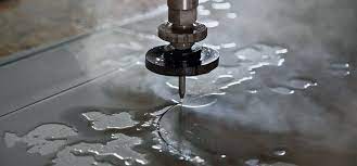
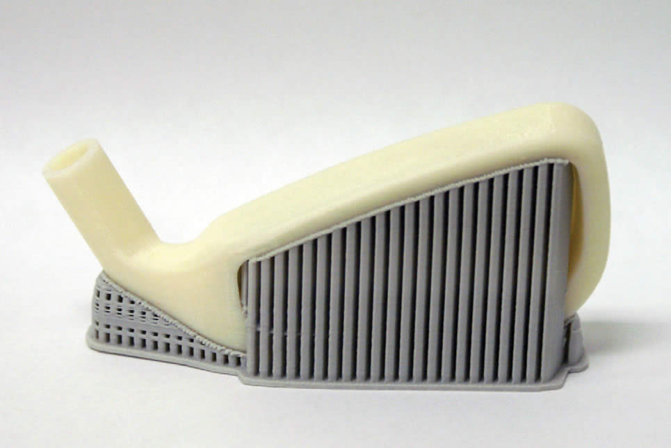
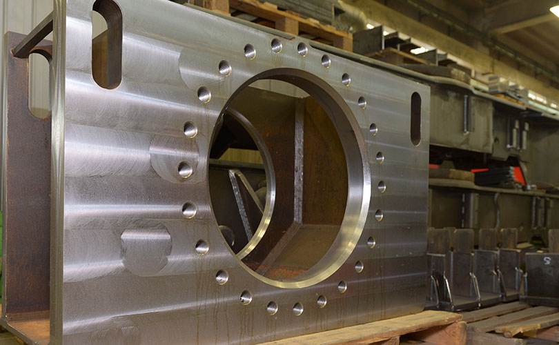
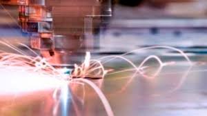
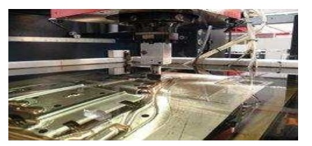
•   Electrical Discharge `Machining (EDM) •   Wire Cut Electrical Discharge Machining (WCEDM) Electrical Discharge `Machining (EDM) Electrical discharge machining (EDM) is one of the most widely used non-traditional machining processes.  The main  attraction  of EDM  over  traditional  machining  processes such as metal cutting using different tools and grinding is that this technique utilizes thermoelectric  process  to erode  undesired  materials  from  the  work  piece  by a series  of discrete  electrical  sparks  between  the  workpiece  and  the  electrode.  A picture of  EDM machine in operation The traditional machining processes rely on harder tool or abrasive material to remove the  softer  material  whereas  non-traditional   machining   processes  such  as  EDM  uses electrical  spark or thermal  energy  to erode unwanted  material  in order to create desired shape.So, the hardness of the material is no longer a dominating factor for EDM process. A schematic of an EDM process is shown in Figure 2, where the tool and the workpiece are immersed in a dielectric fluid. Figure: Schematic of EDM process EDM  removes  material  by  discharging  an  electrical  current,  normally  stored  in  a capacitor bank, across a small gap between the tool (cathode) and the workpiece (anode) typically in order Application of EDM The EDM process has the ability to machine hard, difficult-to-machine materials. Parts with complex, precise and irregular shapes for forging, press tools, extrusion dies, difficult internal shapes for aerospace and medical applications can be made by EDM process. Some of the shapes madeby EDM process are shown in Figure. Figure: Difficult internal parts made by EDM process Working principle of EDM As shown in Figure 1, at the beginning of EDM operation, a high voltage is applied across the narrow gap between the electrode and the workpiece. This high voltage induces an electric field in the insulating dielectric that is present in narrow gap between electrode and workpiece. This causeconducting particles suspended in the dielectric to concentrate at the points of strongest electrical field. When the potential difference between the electrode and the workpiece is sufficiently high, the dielectric breaks down and a transient spark discharges through the dielectric fluid, removingsmall amount of material from the workpiece surface. The volume of the material removed per spark discharge is typically in the range of 10 -6 to 10-6 mm3. The material removal rate, MRR, in EDM is calculated by the following formula: MRR = 40 I / Tm 1.23     (cm3/min) Where, I is the current amp, TM is the melting temperature of workpiece in 0C Advantages of EDM The main advantages of DM are: •    By this process, materials of any hardness can be machined; •    No burrs are left in machined surface; •    One of the main advantages of this process is that thin and fragile/brittle components can be machined without distortion; •     Complex internal shapes can be machined Limitations of EDM The main limitations of this process are: •    This process can only be employed in electrically conductive materials; •    Material removal rate is low and the process overall is slow compared to conventional machining processes; •    Unwanted erosion and over cutting of material can occur; •    Rough surface finish when at high rates of material removal. Dielectric fluids Dielectric fluids used in EDM process are hydrocarbon oils, kerosene and deionised water. The functions of the dielectric fluid are to: •    Act as an insulator between the tool and the workpiece. •    Act as coolant. •    Act as a flushing medium for the removal of the chips. The electrodes for EDM process usually are made of graphite, brass, copper and copper- tungsten alloys. Design considerations for EDM process are as follows: •    Deep slots and narrow openings should be avoided. •    The surface smoothness value should not be specified too fine….

Read More

ULTRASONIC MACHINING (USM)

Introduction USM is mechanical material removal process or an abrasive process used to erode holes or cavities on hard or brittle work piece by using shaped tools, high frequency mechanical motion and an abrasive slurry. USM offers a solution to the expanding need for machining brittle materials such as single crystals, glasses and polycrystalline ceramics, and increasing complex operations to provide intricate shapes and work piece profiles. It is therefore used extensively in machining hard and brittle materials that are difficult to machine by traditionalmanufacturing processes. The hard particles in slurry are accelerated toward the surface of the work piece by a tool oscillating at a frequency up to 100 KHz – through repeated abrasions, the tool machines a cavity of a cross section identical to its own. Figure: Schematic of ultrasonic machine tool USM is primarily targeted for the machining of hard and brittle materials (dielectric or conductive) such as boron carbide, ceramics, titanium carbides, rubies, quartz etc. USM is a versatile machining process as far as properties of materials are con cerned. This process is able toeffectively machine all materials whether they are electrically conductive or insulator. For an effective cutting operation, the following parameters need to be carefully considered: •    The machining tool must be selected to be highly wear resistant, such as high-carbon steels.  •    The abrasives (25-60 µm in dia.) in the (water-based, up to 40% solid volume) slurry Includes: Boron carbide, silicon carbide and aluminum oxide. Applications The beauty of USM is that it can make non round shapes in hard and brittle materials. Ultrasonically machined non round-hole part is shown in Figure 11. Figure: A non-round hole made by USM Advantage of USM USM process is a non-thermal, non-chemical, creates no changes in the microstructures, chemical or physical properties of the work piece and offers virtually stress free machined surfaces. •    Any materials can be machined regardless of their electrical con ductivity •    Especially suitable for machining of brittle materials •    Machined parts by USM possess better surface finish and higher structural integrity. •    USM does not produce thermal, electrical and chemical abnormal surface Disadvantages of USM •    USM has higher power consumption and lower material-removal rates than traditional Fabrication processes. •    Tool wears fast in USM. •    Machining area and depth is restraint in USM.

Read More

ABRASIVE WATER-JET MACHINING (AWJM)

Introduction Abrasive water jet cutting is an extended version of water jet cutting; in which the water jet contains abrasive particles such as silicon carbide or aluminum oxide in order to increase the  material  removal  rate  above  that  of  water  jet  machining.  Almost  any  type  of  material ranging  from  hard  brittle  materials  such  as  ceramics,  metals  and  glass  to  extremely  soft materials such as foam and rubbers can be cut by abrasive water jet cutting. The narrow cutting stream and computer controlled movement enables this process to produce parts accurately and efficiently. This machining process is especially ideal for cutting materials that cannot be cut by laser or thermal cut. Metallic, non-metallic and advanced composite materials of various thicknesses can be cut by this process. This process is particularly suitable for heat sensitive materials that cannot be machined by processes that produce heat while machining. The schematic of abrasive water jet cutting is shown in Figure 15 which is similar to water jet cutting apart from some more features underneath the jewel; namely abrasive, guard and mixing tube. In this process, high velocity water exiting the jewel creates a vacuum which sucks abrasive from the abrasive line, which mixes with the water in the mixing tube to form a high velocity beam of abrasives Applications Abrasive  water  jet  cutting  is  highly  used  in  aerospace,  automotive  and  electronics industries. In aerospace industries, parts such as titanium bodies for military aircrafts, engine components (aluminium, titanium, and heat resistant alloys), aluminum body parts andinteriorcabin parts are made using abrasive water jet cutting. In automotive industries, parts like interior trim (head liners, trunk liners, and door panels) and  fiber  glass  body  components  and  bumpers  are  made  by  this  process.  Similarly,  in electronics industries, circuit boards and cable stripping are made by abrasive water jet cutting. Advantages of abrasive water jet cutting •       In most of the cases, no secondary finishing required •       No cutter induced distortion •       Low cutting forces on work pieces •       Limited tooling requirements •       Little to no cutting burr •       Typical finish 125-250 microns •       Smaller kerf size reduces material wastages •       No heat affected zone •       Localizes structural changes •       No cutter induced metal contamination •       Eliminates thermal distortion •       No slag or cutting dross •       Precise, multi plane cutting of contours, shapes, and bevels of any angle. Limitations of abrasive water jet cutting •       Cannot drill flat bottom •       Cannot cut materials that degrades quickly with moisture •       Surface finish degrades at higher cut speeds which are frequently used for rough cuts The major disadvantages of abrasive water jet cutting are high capital cost and high noise levels during operation. A component cut by abrasive water jet cutting is shown in Figure .As it can be seen, large parts can but cut with very narrow kerfs which reduces material wastages. The complex shape part made by abrasive water jet cutting Abrasive water jet cutting •    WJM – Pure •    WJM – with stabilizer •    AWJM – entrained – three phase –abrasive, water and air •    AWJM – suspended – two phase –abrasive and water o direct pumping i. Indirect Pumping ii. Bypass pumping

Read More

WATER JET MACHINING (WJM)

Introduction Water  jet  cutting  can  reduce  the  costs  and  speed  up  the  processes  by  eliminating  or reducing expensive secondary machining process. Since no heat is applied on the materials, cut edges are clean with minimal burr. Problems such as cracked edge defects, crystallization, hardening, reduced weldability and machinability are reduced in this process. Water jet technology uses the principle of pressurizing water to extremely high pressures, and allowing the water to escape through a very small opening called “orifice” or “jewel”. Water jet cutting uses the beam of water exiting the orifice to cut soft materials. This method is not suitable for cutting hard materials. The inlet water is typically pressurized between 1300 – 4000 bars. This high pressure is forced through a tiny hole in the je el, hich is typically 0.18 to 0.4 mm in diameter. Picture of water jet chinning process. Applications Water jet cutting is mostly used to cut lower strength materials such as wood, plastics and aluminum. When abrasives are added, (abrasive water jet cutting) stronger materials such as steel and tool steel. Advantages of Water Jet Cutting •   There is no heat generated in water jet cutting; which is especially useful for cutting    tool steel and other metals where excessive heat may change the properties of the material. •   Unlike machining or grinding, water jet cutting does not produce any dust or particles that are harmful if inhaled. •   Other advantages are similar to abrasive water jet cutting Disadvantages of water jet cutting •   One of the main disadvantages of water jet cutting is that a limited number of materials can be cut economically. •   Thick parts cannot be cut by this process economically and accurate ly •   Taper is also a problem with water jet cutting in very thick materials. Taper is when the jet exits the part at different angle than it enters the part, and cause dimensional inaccuracy.

Read More

Modeling of material removal

Material removal in AJM takes place due to brittle fracture of the work material due to impact of high velocity abrasive particles. Modeling has been done with the following assumptions: (i) Abrasives are spherical in shape and rigid. The particles are characterized by the mean grit diameter (ii) The kinetic energy of the abrasives are fully utilized in removing material (iii) Brittle materials are considered to fail due to brittle fracture and the fracture volume is considered to be hemispherical with diameter equal to choral length of the indentation (iv) For ductile material, removal volume is assumed to be equal to the indentation volume due to particulate impact

Read More

Process Parameters and Machining Characteristics

Abrasive:  Material – Al2O3 / SiC / glass beads Shape – irregular / spherical Size – 10 ~ 50 μm Mass flow rate – 2 ~ 20 gm/min Carrier gas: Composition – Air, CO2, N2 Density – Air ~ 1.3 kg/m3 Velocity – 500 ~ 700 m/s Pressure – 2 ~ 10 bar Flow rate – 5 ~ 30 lpm Abrasive Jet : Velocity – 100 ~ 300 m/s Mixing ratio – mass flow ratio of abrasive to gas Stand-off distance – 0.5 ~ 5 mm Impingement Angle – 60  ~    90 Nozzle: Material – WC Diameter – (Internal) 0.2 ~ 0.8 mm Life – 10 ~ 300 hours

Read More

ABRASIVE JET MACHINING (AJM)

In Abrasive Jet Machining (AJM), abrasive particles are made to impinge on the work material at a high velocity. The high velocity abrasive particles remove the material by micro- cutting action as well as brittle fracture of the work material. In AJM, generally, the abrasive particles of around 50 μm grit size would impinge on the work material at velocity of 200 m/s from a nozzle of I.D. of 0.5 mm with a standoff distance of around 2 mm. The kinetic energy of the abrasive particles would be sufficient to provide materialremoval due to brittle fracture of the work piece or even micro cutting by the abrasives.            Schematic Arrangement of AJM      

Read More

BRIEF OVERVIEW

1 ULTRA SONIC MACHINING USM is a mechanical material removal process in which the material is removed by repetitive impact of abrasive particles carried in liquid medium on to the work surface, by a shaped tool, vibrating at ultrasonic frequency. 2 ABRASIVE JET MACHINING It is the material removal process where the material is removed or machined by the impact erosion of the high velocity stream of air or gas and abrasive mixture, which is focused on to the work piece. 3. LASER BEAM MACHINING Laser-beam machining is a thermal material-removal process that utilizes a high- Energy, Coherent light beam to melt and vaporize particles on the surface of metallic and non- Metallic work pieces. Lasers can be used to cut, drill, weld and mark. LBM is particularly suitable for making accurately placed holes. 4. ELECTRON EAM MACHINING It is the thermo-electrical material removal process on which the material is removed by the high velocity electron beam emitted from the tungsten filament made to impinge on the work surface, where kinetic energy of the beam is transferred to the work piece material, producing intense heat, which makes the material to melt or vaporize it locally. 5. ELECTRO CHEMICAL MACHINING It is the controlled removal of metals by the anodic dissolution in an electrolytic medium, where the work piece (anode) and the tool (cathode) are connected to the electrolytic circuit, which is kept, immersed in the electrolytic medium. 6. ELECTO CHEMICAL GRINDING ECG is the material removal process in which the material is removed by the combination of Electro- Chemical decomposition as in ECM process and abrasive due to grinding. 7. PLASMA ARC MACHINING Plasma is defined as the gas, which has been heated to a sufficiently high temperature to become ionized. 8. WATER JET MACHINING Water jet cutting can reduce the costs and speed up the processes by eliminating or reducing expensive secondary machining process. Since no heat is applied on the materials, cut edges are clean with minimal burr. Problems such as cracked edge defects, crystallization, hardening, reduced weldability and machinability are reduced in this process. 9. ELECTRICAL DISCHARGE MACHINING EDM is the controlled erosion of electrically conductive materials by the Initiation of rapid and repetitive spark discharge between the electrode tool to the cathode and work to anode separated by a small gap kept in the path of dielectric medium. This Process also called spark erosion.

Read More

CLASSIFICATION OF UCM PROCESSES

1.     Mechanical Processes •          Abrasive Jet Machining (AJM) •          Abrasive Water Jet Machining (AWJM) •          Water Jet Machining (WJM) •          Ultrasonic Machining (USM)              2. Electrochemical Processes •          Electrochemical Machining (ECM) •          Electro Chemical Grinding (ECG) •          Electro Jet Drilling (EJD) 3. Electro-Thermal Processes •          Electro-discharge machining (EDM) •          Laser Jet Machining (LJM) •          Electron Beam Machining (EBM) 4. Chemical Processes •          Chemical Milling (CHM) •          Photochemical Milling (PCM)

Read More