Posted inHeat & Mass Transfer
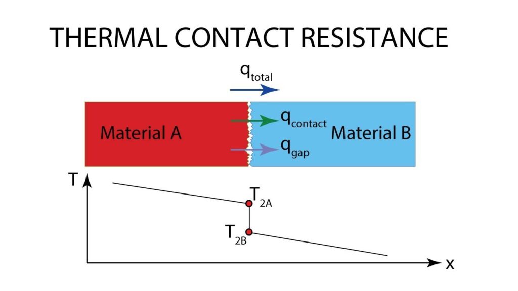
THERMAL CONTACT RESISTANCE
1) Reducing Thermal Contact resistance a) The thermal contact resistance can be minimized by applying thermally conducting…
Engineering the Future, One Mechanism at a Time.