Stepper motors are available in three basic configurations:
1. Universal Stepper Motor-
A universal stepper motor can be connected as a bipolar or a uni-polar stepper motor.
2. Uni-polar Stepper Motor-
A Uni-polar stepper motor can be used as uni-polar or a bipolar stepper motor.
3. Bipolar stepper Motor-
A bipolar stepper motor can only be used as a bipolar.
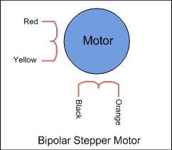
A bipolar stepper motor has one winding per stator phase. A two phase bipolar stepper motor will have 4 leads. In a bipolar stepper we don’t have a common lead like in a uni-polar stepper motor. Hence, there is no natural reversal of current direction through the winding.
A bipolar stepper motor has easy wiring arrangement but its operation is little complex. In order to drive a bipolar stepper, we need a driver IC with an internal H bridge circuit. This is because, in order to reverse the polarity of stator poles, the current needs to be reversed. This can only be done through a H bridge.
There are two other reasons to use an H Bridge IC
1. The current draw of a stepper motor is quite high. The micro-controller pin can only provide up to 15 mA at maximum. The stepper needs current which is around ten times this value. A external driver IC is capable of handling such high currents.
2. Another reason why H Bridge is used is because the stator coils are nothing but inductor. When coil current changes direction a spike is generated. A normal micro-controller pin cannot tolerate such high spikes without damaging itself. Hence to protect micro-controller pins, H bridgeis necessary.
The most common H Bridge IC used in most Bipolar stepper interfacing projects is L293D.
Interfacing to Micro-Controller
4 micro-controller pins are required to control the motor. We need to provide the L293D with 5 V supply as well as the voltage at which the motor needs to operate. Since we will be using both the drivers of the IC, we will assert the enable pin for both of them.
Interfacing Diagram

There are three different ways in which we can drive the bipolar stepper motor-
1. Only one of the phase winding are energized at a time. That is, either AB or CD is energized. Of course the coils will be energized in such a way that we get correct polarity. But only one phase is energized. This type of stepping will give less holding torque because only one phase is energized.
2. In this method, both the phases are activated at the same time. The rotor will align itself between two poles. This arrangement will give higher holding torque than the previous method.
3. The third method is used for half stepping. This method is used generally to improve the stepping angle. Here, in step 1 only 1 phase is ON, then in step 2, 2 phases are ON, then again only one phase is ON and the sequence continues.
Many companies have started assembling their own bipolar stepper drives. Care must be taken that you connect the stepper motor correctly to the drive. Also the drive must be able to supply sufficient current for you stepper. The micro-controller must only provide the step and direction signal to the drive. This method will occupy only two micro-controller pins and is very helpful in projects that require large number of micro-controller pins for other functions.
Unipolar Stepper v/s Bipolar Stepper
Both uni-polar and Bipolar steppers are used widely in projects. However, they have their own advantages and disadvantages from the application point of view. The advantage of a uni-polar motor is that we do not have to use a complex H bridge circuitry to control the stepper motor. Only a simple driver like ULN2003A will do the task satisfactorily. But, there is one disadvantage of uni-polar motors. The torque generated by them is quite less. This is because the current is flowing only through the half the winding. Hence they are used in low torque applications.
On the other hand, bipolar stepper motors are a little complex to wire as we have to use a current reversing H bridge driver IC like an L293D. But the advantage is that the current will flow through the full coil. The resulting torque generated by the motor is larger as compared to a uni-polar motor.


