The classification of electrical drives can be done depending upon the various components of the drive system. Now according to the design, the drives can be classified into three types such as single-motor drive, group motor drive and multi motor drive. The single motor types are the very basic type of drive which are mainly used in simple metal working, household appliances etc. Group electric drives are used in modern industries because of various complexities. Multi motor drives are used in heavy industries or where multiple motoring units are required such as railway transport. If we divide from another point of view, these drives are of two types:
1. Reversible types drives
2. Non reversible types drives.
This depends mainly on the capability of the drive system to alter the direction of the flux generated. So, several classification of drive is discussed above.
Parts of Electrical Drives
The diagram which shows the basic circuit design and components of a drive, also shows that, drives have some fixed parts such as, load, motor, power modulator, control unit and source. These equipments are termed as parts of drive system. Now, loads can be of various types i.e they can have specific requirements and multiple conditions, which are discussed later, first of all we will discuss about the other four parts of electrical drives i.e motor, power modulator, source and control unit.
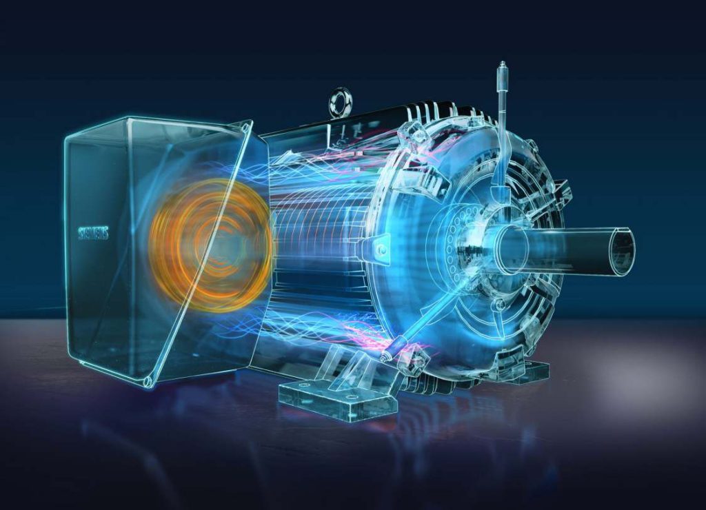
Electric motors are of various types. The DC motors can be divided in four types – shunt wound DC motor, series wound DC motor, compound wound dc motor and permanent magnet DC motor. AC motors are of two types – induction motors and synchronous motors. Now synchronous motors are of two types – round field and permanent magnet. Induction motors are also of two types – squirrel cage and wound motor. Besides all of these, stepper motors and switched reluctance motors are also considered as the parts of drive system.
So, there are various types of electric motors, and they are used according to their specifications and uses. When the electrical drives were not so popular, induction and synchronous motors were usually implemented only where fixed or constant speed was the only requirement. For variable speed drive applications, DC motors were used. But as we know that, induction motors of same rating as a DC motors have various advantages like they have lighter weight, lower cost, lower volume and there is less restriction on maximum voltage, speed and power ratings. For these reasons, the induction motors are rapidly replaced the DC motors. Moreover induction motors are mechanically stronger and require less maintenance. When synchronous motors are considered, wound field and permanent magnet synchronous motors have higher full load efficiency and power factorthan induction motors, but the size and cost of synchronous motors are higher than induction motors for the same rating.
Brush less DC motors are similar to permanent magnet synchronous motors. They are used for servo applications and now a days used as an effcient alternative to DC servo motors because they don’t have the disadvantages like commentation problem. Beside of these, stepper motors are used for position control and switched reluctance motors are used for speed control.
Power Modulators – are the devices which alter the nature or frequency as well as changes the intensity of power to control electrical drives. Roughly, power modulators can be classified into three types,
1. Converters,
2. Variable impedance circuits,
3. Switching circuits.
As the name suggests, converters are used to convert currents from one type to other type. Depending on the type of function, converters can be divided into 5 types –
1. AC to DC converters
2. AC regulators
3. Choppers or DC – DC converters
4. Inverters
5. Cycloconverters
AC to DC converters are used to obtain fixed DC supply from the AC supply of fixed voltage. The very basic diagram of AC to DC converters is like.
AC Regulators are used to obtain the regulated AC voltage, mainly autotransformers or tap changer transformers are used in this regulators.
Choppers or DC – DC converters are used to get a variable DC voltage. Power transistors, IGBT’s, GPO’s, power MOSFET’s are mainly used for this purpose.

Inverters are used to get AC from DC, the operation is just opposite to that of AC to dc converters. PWM semiconductors are used to invert the current.

Cycloconverters are used to convert the fixed frequency and fixed voltage AC into variable frequency and variable voltage AC. Thyristors are used in these converters to control the firing signals. 
Variable Impedance circuits are used to controlling speed by varying the resistance or impedance of the circuit. But these controlling methods are used in low cost DC and ac drives. There can be two or more steps which can be controlled manually or automatically with the help of contactors. To limit the starting current inductors are used in AC motors.
Switching circuits in motors and electrical drives are used for running the motor smoothly and they also protects the machine during faults. These circuits are used for changing the quadrant of operations during the running condition of a motor. And these circuits are implemented to operate the motor and drives according to predetermined sequence, to provide interlocking, to disconnect the motor from the main circuit during any abnormal condition or faults.
Sources may be of 1 phase and 3 phase. 50 Hz AC supply is the most common type of electricity supplied in India, both for domestic and commercial purpose. Synchronous motors which are fed 50 Hz supply have maximum speed up to 3000 rpm, and for getting higher speeds higher frequency supply is needed. Motors of low and medium powers are fed from 400 V supply, and higher ratings like 3.3 kv, 6.6 kv, 11 kv etc are provided also.
Control Unit –
Choice of control unit depends upon the type of power modulator that is used. These are of many types, like when semiconductor converters are used, then the control unit consists of firing circuits, which employ linear devices and microprocessors.
So, the above discussion provides us a simple concept about the several parts of electrical drive.
Advantages of Electrical Drives
Electrical drives are readily used these days for controlling purpose but this is not the only the advantage of Electrical drives. There are several other advantages which are listed below –
1. These drives are available in wide range torque, speed and power.
2. The control characteristics of these drives are flexible. According to load requirements these can be shaped to steady state and dynamic characteristics. As well as speed control, electric braking, gearing, starting many things can be accomplished.
3. The are adaptable to any type of operating conditions, no matter how much vigorous or rough it is.
4. They can operate in all the four quadrants of speed torque plane, which is not applicable for other prime movers.
5. They do not pollute the environment.
6. They do not need refueling or preheating, they can be started instantly and can be loaded immediately.
7. They are powered by electrical energy which is atmosphere friendly and cheap source of power.
Because of the above mentioned advantages of electrical drives, they are getting more and more popular and are used in a wider range of applications.


