Model for a closed, manifold and correctly shelled mesh
If your plan is to get your hands on an object you designed through Sculpteo’s 3d printing program, you need to produce a 3D mesh file and export it in any of the acceptable formats, usually a .stl file.
Mesh files are not necessarily used for 3D printing, so it is important to use characteristics that function with the program you plan on using it for, whether that be rendering, animation, or 3D printing. The most important characteristics for a 3D printing mesh (also the most common errors for non-printable meshes) are that must be manifold, oriented, and made of single shell parts. We recommend modeling with Autodesk Inventor as these characteristics are easily attainable.
Manifold essentially means that your mesh needs to be completely closed (Or ‘watertight’) and that each of its edges needs to be shared with two polygons. A solid in Inventor always produces this type of mesh; if it doesn’t, that means your current model is not yet a solid but a group of surfaces. It’s easy to recognize when your imported model is made of a solid or multiple surfaces because multiple surfaces do not look the same – they have a slightly transparent shade by default.

That type of problem can occur if a model is imported from another software, and then its converted to a .stl file or if surfaces are created directly in Inventor. If the element in Inventor is not a solid, the 3D Print Preview won’t allow us to export the model and will produce this message:

If this message appears, all we need to do in order to obtain a solid that is exportable as a manifold mesh, is to stitch these surfaces together using the command ‘Stitch’  (Press the command>select the surfaces>press ‘Apply’>press ‘Done’).
As for the orientation of the mesh, the inside and outside of a solid model are automatically determined. That which is mathematically full within the solid is defined as the internal area and there is no reason to manually define it.
The third important requirement is to have each separate part of our model made of just one shell. Once again, the software automates this process, and each time we create a new feature on the working model, a joining option can be chosen (Join  Cut or
 Intersect
  ).
).
Otherwise, selecting ‘New solid’ when creating a new feature, produces what will be recognized as a separate shell in the mesh. To join two solids into one (And obtain one shell when meshed), the command ‘Combine’  is needed (Press the command>Select bodies to be joined>choose Join, Cut, or Intersect>press ‘Apply’).
Hollow your model with patterns
There are several reasons why digital models for 3D printing should be hollowed but the main one regards the amount of material used to produce it. In 3D printing, unlike common production techniques, the cost to fabricate an object is not dictated by its shape complexity, but mainly by the amount of material that it requires. Making your object hollow will then strongly affect your product costs, sometimes decreasing it by up to 60 or 70%.
Another important reason to hollow your model is to keep your product lightweight if that’s a factor you are aiming for.
But just hollowing your model doesn’t affect your product if your hollowed part is not connected to the outside through at least two holes. The reason is related to the technology: “unprinted” material would be trapped inside your model with no way for it to escape.
Sculpteo has released a fabulous hollowing feature that allows you to do this operation online, simply by choosing the position of the holes on your model. You can upload your 3D file and try it now.
In many examples of successful 3D printed products, we have seen designers taking advantage of this production driven restriction, creating patterns of cavities along the whole model surface. This confers aesthetic factors while reducing the amount of material and therefore the costs of the product. How can this be achieved with Inventor?
We are creating a simple cube (Primitive Box) and choosing one of its faces as 2D Sketch plane (  ).
).


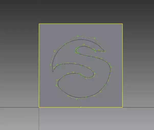
Then press the ‘Insert AutoCAD File’ button (  ) to import the vectorial drawing you want to use as a cutting pattern on the surface (You can also import other types of files or draw something directly on the sketch plane).
We’ve uploaded the Sculpteo logo, then scaled it (  ) and moved it (
  ) to the center of the surface.

Then what we need to do is to use the command ‘Project to 3D Sketch’ (  ) and select the surface on which the sketch is lying. Press OK and exit the sketch (
  ).
).
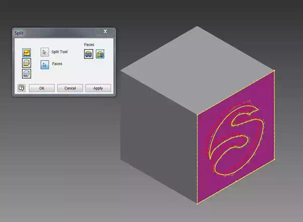
We are then able to separate the area of the logo from the rest of the surface through the feature ‘Split’. Select the 3D Sketch just created with the ‘Split Tool’ and the surface which it belongs to as ‘Faces’. Press ‘Apply’.

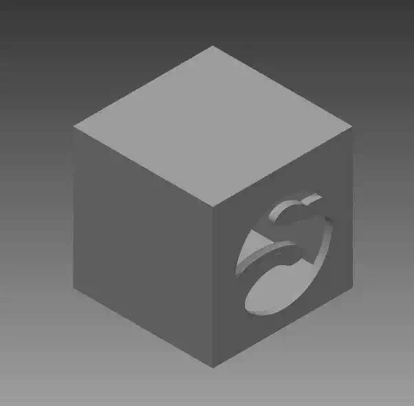
The final step is to use the feature ‘Shell’ to hollow the model, removing the logo’s surface just created.
Pick the ‘Shell’ feature (  ) and select the face to remove. Deselect ‘automatic face chain’ if this face belongs to a bigger surface as in this case, and choose the wall thickness you want to achieve, depending on the material. For instance, Plastic material needs to be at least 0.8 mm and 2 mm to be considered as rigid. You can find more information about material specifications on our Materials page.
Now you can press ‘Apply’ to hollow the model, and engrave the logo.


