
Inventor allows us to very easily color the singular faces of our model or apply materials to them, but unfortunately, it doesn’t allow us the ability to export this information as proper files for Full Color 3D Printing.
To partially avoid this problem, ‘CadStudio’ created a plug-in called ‘VRML Translator for Inventor’, which gives the ability to export as a VRML file. VRML files keep track of color information and it’s accepted by Sculpteo uploader. You can find it on ‘CadStudio’ page (Trial version free, after 99 Euros).
However, this only partially solves the problem because VRML still do not support textures; it’s still not possible to make the most of the Full Color printing technology.
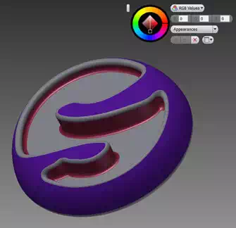
When you have installed the plug-in (instructions in the link above), you can easily apply colors to your model with the command ‘Adjust’ tool, and select a color directly from the color picker or by entering an RGB value, and choosing the faces where will be applied. With the above mentioned plug-in, a VRML will appear among the available exporting formats, and your colors will be stored in the file!
1.4. Measure the model
The first way to check if we have modeled correctly, and respected the design rules, is to manually do so by creating a new sketch in the model.
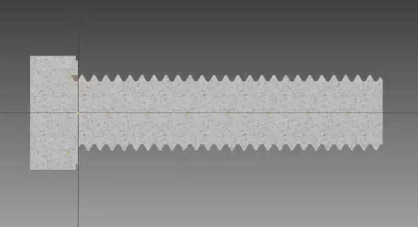
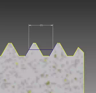
Let’s check for example the pitch of a thread. Choose ‘Create 2D Sketch’ (  ) and select the plane that is longitudinally crossing the bolt model then go to the cutaway view of the model by right click>Slice Graphic, to be able to evaluate the profile of the thread.
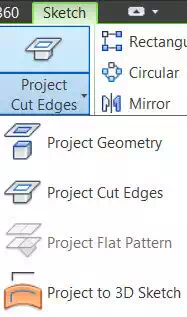
Let’s show its edges in the sketch with the command ‘Project Cut Edges’, that you can find in the ‘Project Geometry’ tab. This way, you would be able to snap to the geometry of your model that is intersecting the plane you chose.
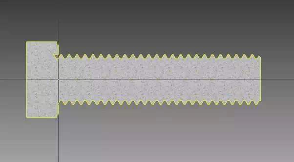
Now with the tool ‘Line’ (  ) you can trace two consecutive oblique faces of the thread and connect their middle points. Use the tool ‘Dimension’ (
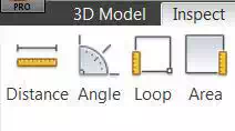
  ) to measure the length of this line, and if it corresponds to your thread Pitch, it means you’ve modeled correctly. If what you want to measure is the distance or the angle between edges, points or faces of the model, or check the size of areas and loops of the faces, you should then access the features called ‘Measure’ under the ‘Inspect’ panel.
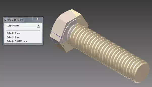
For example, it could be really important to check the wall thickness of your object at the end of modeling. Anything lower than 0.8 mm won’t, in fact, be 3D printable in any material. You can find more information about materials and their specifications on our Materials page.
You can measure it with the ‘Distance’ (  ) tool, selecting two opposite faces of a wall, and read their distance (Wall thickness) in the active window.
