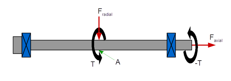
The shaft is a basic mechanical component of many machines. This article will discuss drive shaft design concepts and formulas by explaining a design problem for a shaft for a constant load.
You can see a shaft in almost every machine which has rotating parts. Typically a shaft has a circular cross section. However, the shaft with other cross-sections find special application. We will discuss the design concept of a drive shaft subjected to a fixed load.
A drive shaft is supported by bearings at both the ends (and at regular interval in the centre for longer shafts). The belt driven pulleys are usually placed over the shaft in between the bearings.
Basic Shaft Design Formula
The drive shaft with multiple pulleys experience two kinds of stresses, bending stress and shear stress. The maximum bending stress generated at the outermost fiber of the shaft. And on the other hand, the shear stress is generated at the innermost fiber. Also, the value of maximum bending stress is much more than the shear stress. So, the design of the shaft will be based on the maximum bending stress and will be driven by the following formula:
Maximum bending stress Tb = (M * r) / I……………….Eqn.1.1
Where,
M is maximum bending moment on the shaft.
r is the radius of the shaft.
I is area moment of inertia of the shaft.
Design Procedure
○ Draw the bending moment diagram to find out the maximum bending moment (M) on the shaft.
○ Calculate the area moment of inertia (I) for the shaft.
○ Replace the maximum bending stress (Tb) with the given allowable stress for the shaft material.
○ Calculate the radius of the shaft.
Shaft Design Problem

Refer the above picture, where a steel shaft is supported by two bearings and a pulley is placed in between the bearings. You have to design the shaft. Weight of the pulley is 1000 N.
Input data:
Maximum allowable shear stress for the shaft material= 40 Nmm.
Solution:
○ From the bending moment diagram, the maximum bending moment (M) is calculated as 66666.67 Nmm.
○ Area moment of inertia (I)of the circular shaft is:
I = pi * r^4 *0.25
= 0.785*r^4………………..Eqn. 1.2
○ From Eqn1.1 we can write:
40 = (66666.67 *r)/ (0.785*r^4)
r= 12.85 mm
○ So, the minimum radius of the shaft should be 12.85 or 13 mm.
Conclusion
The drive shaft design problem discussed in this article has considered only the self weight of the pulley and hence the load acting in only one direction. If the loads act in multiple directions then the resultant moments need to be calculated and then the shaft design formula applied. Another way of solving drive shaft design concept problem is using FEA tools.


