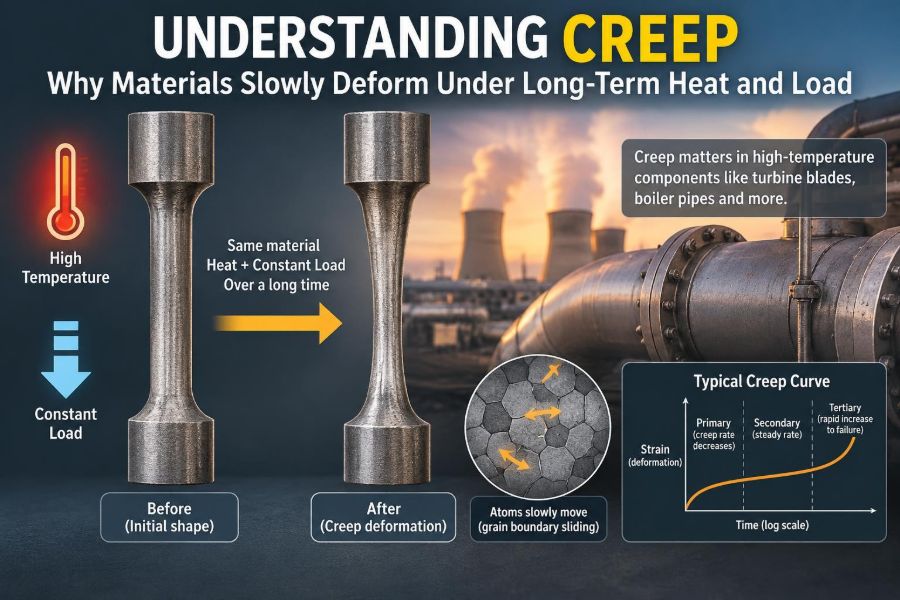

A steam pipe in a power plant can look perfectly sound for years, even while its metal is gradually changing shape under pressure and heat. A turbine blade may keep turning at high speed, yet lengthen by an almost imperceptible amount during service. Neither component needs a dramatic overload to begin accumulating damage.
This slow, time-dependent deformation is called creep. It is one of the reasons engineers must think beyond a material’s strength measured during a quick tensile test. A part can safely carry a load for minutes and still become unsafe when it carries that same load for tens of thousands of hours at elevated temperature.
Creep matters wherever heat and sustained stress meet: boilers, jet engines, furnaces, chemical-processing equipment, electronic solder joints, and even some polymer products. Understanding it helps engineers choose materials, set operating limits, inspect equipment intelligently, and avoid failures that develop quietly.
The central lesson is simple: materials are not always dimensionally permanent under load. Given enough temperature and time, their internal structure can rearrange—and that rearrangement can become a design-limiting problem.
🧭 What Creep Means in Engineering
Creep is permanent deformation that increases with time while a material is under sustained stress. The stress may remain approximately constant, but strain—the fractional change in length or shape—continues to grow.
It differs from elastic deformation, which disappears when a load is removed. Creep also differs from ordinary plastic deformation caused by a single overload. A creeping component can deform at stresses below the yield strength measured in a short, room-temperature test.
Engineers often discuss creep in tension because it is easy to visualize a bar becoming longer. In real equipment, creep can also cause bending, bulging, sagging, distortion, loss of bolt preload, and gradual closure or opening of clearances.
🌡️ Why Temperature Changes the Problem
Atoms in a solid are never completely still. As temperature rises, thermal energy makes it easier for atoms, vacancies, and crystal defects to move. That mobility allows the material to slowly redistribute strain under a continuing load.
A useful rule of thumb is that creep becomes a serious concern for many metals above roughly 0.4 times their absolute melting temperature, where temperature is expressed in kelvin. This is only a screening guide, not a universal threshold; alloy type, stress, environment, and required service life all matter.
For polymers, meaningful creep can occur at much lower everyday temperatures because their molecular chains are more mobile. A plastic shelf that gradually sags under stored weight is a familiar low-temperature example of time-dependent deformation.
⏳ Why Time Is a Design Variable
Most introductory strength calculations compare stress with yield strength or ultimate tensile strength. Those values come from relatively short tests, so they cannot by themselves describe what happens over years of service.
With creep, a component’s safe stress depends on the intended duration. A tube that performs acceptably for a short startup cycle may accumulate unacceptable strain over prolonged high-temperature operation.
This makes operating history valuable. Total hot hours, temperature excursions, load cycles, and periods near the maximum permitted temperature can all affect remaining life. Time is not merely a maintenance record; it is part of the loading condition.
📈 Reading a Typical Creep Curve
A creep test commonly holds a specimen at constant temperature and stress while measuring strain over time. The resulting curve reveals that creep rate is usually not constant throughout life.
The curve is often divided into three recognizable stages: primary, secondary, and tertiary creep. This classification helps engineers connect observed deformation with the changing competition between strengthening and damage processes inside the material.
Primary, secondary, and tertiary behavior
- Primary creep: the creep rate decreases as the material strain-hardens or otherwise develops resistance to further deformation.
- Secondary creep: the rate becomes approximately steady. This stage is often called steady-state creep and is central to long-term design.
- Tertiary creep: the rate accelerates because damage such as voids, cracks, necking, or grain-boundary weakening reduces the load-bearing area.
Not every material or test produces perfectly separated stages. Still, the framework is useful for interpreting behavior and recognizing why rapid deformation late in life is especially concerning.
⚖️ Stress Still Matters, Even Below Yield
Higher stress generally produces faster creep and a shorter rupture life. The relationship is often highly nonlinear: a modest increase in stress can greatly change the time required to reach a specified strain or failure condition.
Geometry therefore matters. A local stress concentration at a weld toe, hole, sharp transition, or misaligned support can creep faster than the nominal stress calculation suggests. As the area changes through deformation, the local stress state may change too.
Designers must consider actual service stresses, including internal pressure, self-weight, thermal restraint, residual stress, and occasional loads. Looking only at one load source can hide the critical combination.
🔬 What Happens Inside a Creeping Metal
Metal crystals contain defects such as dislocations, which are line-like irregularities in the atomic arrangement. Plastic deformation occurs when dislocations move. At high temperature, they can bypass obstacles through thermally activated processes, allowing strain to accumulate under lower stress than would be required at room temperature.
Atoms and vacancies can also diffuse through the lattice or along grain boundaries. Under stress, this diffusion is directional enough to change shape gradually. Cavities may form at grain boundaries, especially where local stress and microstructural weakness combine.
Creep is therefore not one single mechanism. Which mechanism dominates depends on temperature, stress, grain size, alloy composition, and the material’s evolving microstructure.
🧱 Dislocation Creep and Diffusion Creep
At relatively higher stresses, dislocation creep is often important. Dislocations glide and climb around obstacles, with climb aided by diffusion. Alloying particles and stable microstructural features can slow this motion, which is why heat-resistant alloys are carefully engineered.
At lower stresses and sufficiently high temperatures, diffusion creep can dominate. Atoms move from regions under compressive stress toward regions under tensile stress, gradually changing the component’s shape.
Fine-grained materials can be more susceptible to grain-boundary diffusion because they contain more boundary area. That means a microstructure beneficial for room-temperature strength is not automatically ideal for high-temperature creep resistance.
🌾 Why Grain Boundaries Can Become Weak Links
Grain boundaries are interfaces between crystals with different orientations. They can be useful obstacles to dislocation movement at moderate temperatures, but at elevated temperature they may become preferred paths for diffusion and sliding.
Grain-boundary sliding occurs when neighboring grains shift slightly relative to one another. If surrounding material cannot accommodate this movement smoothly, voids and cracks may develop at boundary junctions or around particles.
For some high-temperature applications, engineers prefer coarse-grained or directionally solidified structures because they reduce the number of boundaries crossing the main stress direction. The best choice remains application-specific: toughness, manufacturability, fatigue performance, and corrosion resistance also need consideration.
🕳️ From Microscopic Voids to Creep Rupture
Creep rupture is the final fracture of a material after prolonged exposure to stress and temperature. It commonly begins with microscopic cavities, often at grain boundaries, inclusions, precipitates, or other sites where stress concentrates.
These cavities can grow and link into cracks. In a pressurized tube, a crack may reduce the remaining load-bearing section, raising local stress and accelerating tertiary creep. The transition from slow deformation to failure can therefore become much faster near the end of life.
Visible bulging, distortion, or surface cracking may be late-stage evidence rather than an early warning. Inspection methods aim to identify damage before it reaches that point.
📏 Creep Strain, Creep Rate, and Rupture Life
Three related measures are used for different decisions. Creep strain asks how much permanent deformation has occurred. Creep rate asks how quickly deformation is accumulating. Rupture life asks how long a specimen survives under a defined temperature and stress.
A component may be unacceptable long before rupture. For example, a turbine blade that creeps enough to reduce clearance can rub a casing, while a bolted joint that relaxes can leak even though no part has fractured.
Good design criteria therefore match the real failure mode. Limiting strain, limiting deformation rate, and preventing rupture are related goals, but they are not interchangeable.
🧪 How Engineers Perform Creep Tests
In a conventional uniaxial creep test, a carefully machined specimen is placed in a temperature-controlled furnace and loaded in tension. Extension is recorded over a long period, sometimes until a target strain or rupture is reached.
Test control matters greatly. Small changes in specimen temperature, alignment, load, or atmosphere can alter results. High-temperature testing also requires reliable extensometry and calibration because the strains of interest may be small for much of the test.
Since full-duration tests can be very long, material databases combine many tests across stresses and temperatures. Engineers then use validated material models and code rules to make life predictions within defined limits.
🗂️ How Long-Term Data Are Interpreted
Engineers use time-temperature parameters to organize creep-rupture data and estimate long-duration behavior from sets of shorter and longer tests. The Larson-Miller parameter is a well-known example, though its use requires material-specific judgment and appropriate data.
Extrapolation is unavoidable in many projects, but it carries uncertainty. A material’s mechanism can change at a new temperature or over a much longer time, and a fitted trend may not capture that transition.
For critical equipment, conservative allowable stresses, service experience, inspection findings, and documented operating history are used alongside laboratory data. A smooth graph should never be mistaken for certainty beyond its supported range.
🧮 Why Simple Strength Numbers Are Not Enough
Yield strength answers a short-term question: when does obvious permanent deformation begin under a specified test condition? Creep design asks a different question: how much deformation or damage will accumulate over a defined service life at temperature?
Two alloys can have similar room-temperature tensile strengths yet very different creep resistance. One may retain a stable precipitate structure at heat, while another coarsens or softens and loses its ability to resist dislocation motion.
When selecting a material for hot service, useful data include allowable stress at temperature, creep strain limits, rupture data, oxidation resistance, weldability, thermal expansion, and compatibility with the process environment.
🔥 Creep in Boilers, Pipes, and Pressure Equipment
High-temperature piping and boiler tubes experience internal pressure, thermal gradients, and often substantial operating time. Over years, creep may appear as tube swelling, pipe sagging, or damage in heavily stressed regions such as bends, headers, and weldments.
Temperature control is crucial because local overheating can produce far more damage than average temperature suggests. Deposits on a tube’s internal surface, poor heat transfer, flame misalignment, or altered flow can create localized hot spots.
Pressure systems are governed by detailed design and inspection practices. Actual evaluation should follow the applicable equipment code, material data, plant procedures, and qualified engineering review rather than a generic rule of thumb.
✈️ Creep in Turbines and Jet Engines
Turbine blades, disks, combustor hardware, and other hot-section components operate in demanding combinations of temperature, stress, vibration, and oxidation. Their materials are selected not simply for strength but for resistance to long-term microstructural change.
Nickel-based superalloys are widely used in severe hot sections because their compositions and heat treatments create strengthening phases that resist dislocation motion. Protective coatings and sophisticated cooling passages help lower metal temperature, often providing substantial life benefits.
These parts also face fatigue from starts, stops, and thermal cycling. In service, creep and fatigue can interact, so assessing either mechanism in isolation may be inadequate.
🔩 Why Bolts Relax at High Temperature
A bolted joint works because tightening creates preload, which clamps the parts together. At elevated temperature, creep in the bolt, gasket, or clamped components can reduce that preload over time; this loss is often called stress relaxation.
Reduced preload can allow leakage, joint movement, or uneven load sharing among bolts. Simply applying a higher initial torque is not always a safe solution, because it can overstress threads, flanges, or gaskets during installation or thermal transients.
Material selection, joint stiffness, gasket choice, temperature management, tightening procedure, and planned inspection all influence long-term joint performance.
🧴 Creep Is Not Only a Metal Problem
Polymers can creep under loads that seem modest, especially near their glass-transition temperature or when exposed to heat, moisture, chemicals, or ultraviolet aging. Molecular chains gradually rearrange, causing extension, compression set, or bending.
A plastic bracket supporting a continuous load, an insulation clip near a warm surface, or a polymer seal under compression can all show time-dependent behavior. Polymer creep may be strongly nonlinear and sensitive to temperature changes that appear small in ordinary use.
Some ceramics also exhibit high-temperature creep, particularly in furnaces, thermal barriers, and energy systems. Their excellent room-temperature stiffness does not eliminate the need for long-term high-temperature evaluation.
⚗️ The Environment Can Accelerate Damage
Hot materials rarely operate in a perfectly benign environment. Oxidation can consume material, form brittle scales, or alter surface geometry. Corrosive species may weaken grain boundaries or change the chemistry of protective layers.
Hydrogen-containing, carburizing, sulfidizing, or otherwise aggressive environments can complicate life prediction depending on the alloy and process. The combined condition is often more relevant than temperature and stress alone.
Material compatibility must therefore be checked against the actual fluid, gas composition, impurities, pressure, and temperature profile. A laboratory creep value in air may not represent plant service.
🌡️ Thermal Gradients and Restrained Expansion
Uniform heating lets a free component expand with relatively low thermal stress. Real systems are rarely uniform: one side of a pipe may be hotter, a thick section may heat more slowly than a thin one, and supports may restrain natural movement.
This produces thermal stress on top of mechanical load. Repeated starts and shutdowns add cyclic strain, while long hot holds allow creep relaxation and damage accumulation.
Expansion loops, sliding supports, flexible joints, controlled warm-up procedures, and thoughtful geometry can reduce harmful restraint. These measures do not remove creep, but they can lower the stress that drives it.
🔁 Creep-Fatigue Interaction
Fatigue is damage caused by repeated loading and unloading. Creep is time-dependent deformation under sustained load. High-temperature machinery often experiences both: a component holds load during operation, then sees thermal and mechanical cycling during transients.
A dwell period at high temperature can cause stress relaxation, strain accumulation, grain-boundary damage, or oxidation at crack tips. Conversely, fatigue cracks can create local stress concentrations that speed creep damage.
Because the interaction depends on material, temperature, strain range, hold time, and environment, simplified assumptions should be used cautiously. Components with frequent cycling require a life assessment that reflects their real duty cycle.
📐 Geometry and Constraint Shape Creep Damage
Uniaxial laboratory tests are valuable, but real components often have multiaxial stress states. Thick-walled pressure vessels, welded intersections, notches, and constrained joints can develop combinations of tensile, compressive, and shear stress.
Constraint can suppress visible deformation while increasing local damage tendency. A region that cannot freely strain may experience elevated multiaxial stress and develop cavities in locations not predicted by a simple average-stress calculation.
Finite element analysis can help identify hot spots, but only when material models, boundary conditions, temperature fields, and load histories are realistic. A detailed model with uncertain inputs can still yield misleading precision.
🛠️ Welding Creates a Special Creep Challenge
Welding changes the local microstructure through a heat-affected zone beside the weld metal. It can introduce residual stress, alter precipitates, create mismatched properties, and change grain size. These effects make weldments common locations for creep assessment.
Some steels can develop localized creep damage in the heat-affected zone rather than in the parent metal. The weakest region is not always obvious from appearance or room-temperature strength.
Qualified welding procedures, suitable filler metals, heat treatment where required, careful joint design, and inspection are all part of managing weld creep performance. Repairs deserve the same attention as original fabrication.
🔍 Inspecting Equipment for Creep Damage
Inspection combines visual evidence, dimensional checks, operational data, and nondestructive examination. Technicians may look for bulging, sagging, misalignment, surface cracking, oxide changes, or loss of clearance.
Depending on the component, methods can include ultrasonic testing, radiography, surface crack detection, replication metallography, and hardness measurements. Each method has limitations: a technique that finds surface cracks may miss internal cavities, while an indirect indicator may not establish remaining life alone.
Inspection results are strongest when interpreted with service temperature, pressure, cycles, material records, and previous measurements. Trending a changing dimension can be more informative than a single isolated reading.
📊 Monitoring the Conditions That Drive Creep
Because creep depends strongly on temperature and time, reliable operating data are a form of damage control. Temperature sensors should represent the metal condition as closely as practical, not merely a nearby fluid temperature.
Useful records commonly include hot operating hours, peak temperatures, pressure or load history, start-stop cycles, deviations from normal conditions, and repairs. Instrument errors, sensor placement, and missing data should be considered rather than ignored.
Monitoring does not replace inspection or analysis. It helps identify whether the equipment has experienced conditions that warrant closer evaluation and supports more realistic remaining-life decisions.
🧰 Designing Against Creep
Creep-resistant design begins by defining the duty cycle: expected temperatures, stresses, transients, environment, and required life. The selected material must be evaluated using data appropriate to that range, including applicable design allowables.
Common design strategies include:
- reducing metal temperature through insulation, cooling, or improved heat transfer;
- reducing sustained stress with greater section thickness, better support, or lower pressure where feasible;
- choosing alloys and heat treatments with proven high-temperature stability;
- avoiding sharp stress raisers and poorly restrained thermal expansion;
- designing welds, joints, and transitions for inspectability as well as strength.
There is no universal best material. A more creep-resistant alloy may cost more, be harder to fabricate, or have different corrosion and thermal-expansion behavior. The sound choice balances the entire service condition.
🚫 Common Mistakes in Creep Assessment
One frequent mistake is treating a high room-temperature strength as proof of high-temperature durability. Another is using average fluid temperature while overlooking a localized metal hot spot.
Other avoidable errors include:
- assuming a part is safe because it has not yet visibly deformed;
- extrapolating laboratory trends far beyond available data without accounting for uncertainty;
- ignoring weld zones, supports, and geometric discontinuities;
- counting only pressure stress while omitting thermal restraint or self-weight;
- using generic material properties when the exact grade, heat treatment, or service environment is uncertain.
Creep evaluation rewards disciplined records and conservative assumptions. It is less about finding one decisive number than building a defensible picture of damage drivers.
🧠 A Practical Screening Workflow
When creep may be relevant, begin by identifying parts that are both hot and continuously loaded. Establish their material, geometry, operating temperature range, stress sources, environment, and accumulated service time.
- Confirm whether the temperature range places the material in a potential creep regime.
- Identify the governing concern: deformation, loss of preload, cracking, rupture, clearance loss, or a creep-fatigue combination.
- Review applicable material data, design rules, and operating history.
- Inspect the highest-risk locations, including hot spots, welds, bends, supports, and geometric transitions.
- Use qualified engineering assessment to set monitoring, repair, derating, or replacement actions.
This workflow is a screening framework, not a substitute for equipment-specific design-code calculations or professional fitness-for-service evaluation.
🧩 The Core Principle to Remember
Creep occurs because heat gives a loaded material time and mobility to rearrange internally. Stress supplies the driving force; temperature activates movement; time allows small changes to accumulate into significant strain or damage.
The practical implication is equally clear: safe high-temperature design cannot rely on a single short-term strength value. It requires matching material behavior to the actual temperature, stress state, environment, geometry, operating history, and required life.
When engineers control temperature, reduce sustained stress, select stable materials, accommodate thermal movement, and inspect intelligently, creep becomes a manageable design and maintenance problem rather than an invisible surprise.
Materials may deform slowly under long-term heat and load, but careful engineering makes that slow change measurable, predictable, and controllable. ⚙️🌡️🔍