
A gearbox rarely fails without warning. Long before a tooth breaks or a bearing seizes, the machine may run hotter, sound rougher, vibrate more, or leave metallic particles in its oil. These clues are easy to overlook when production is busy and the gearbox is still turning.
That is what makes premature gear failure so frustrating. The visible failure may be one damaged gear tooth, but the underlying cause often began elsewhere: an unsuitable lubricant, a slightly misaligned shaft, a load spike, or a housing that no longer holds components in the intended position.
For students, gears are often introduced as neat geometry and force diagrams. For working professionals, they are assets expected to transmit power day after day under real conditions: contamination, thermal cycling, changing loads, imperfect installation, and limited maintenance windows.
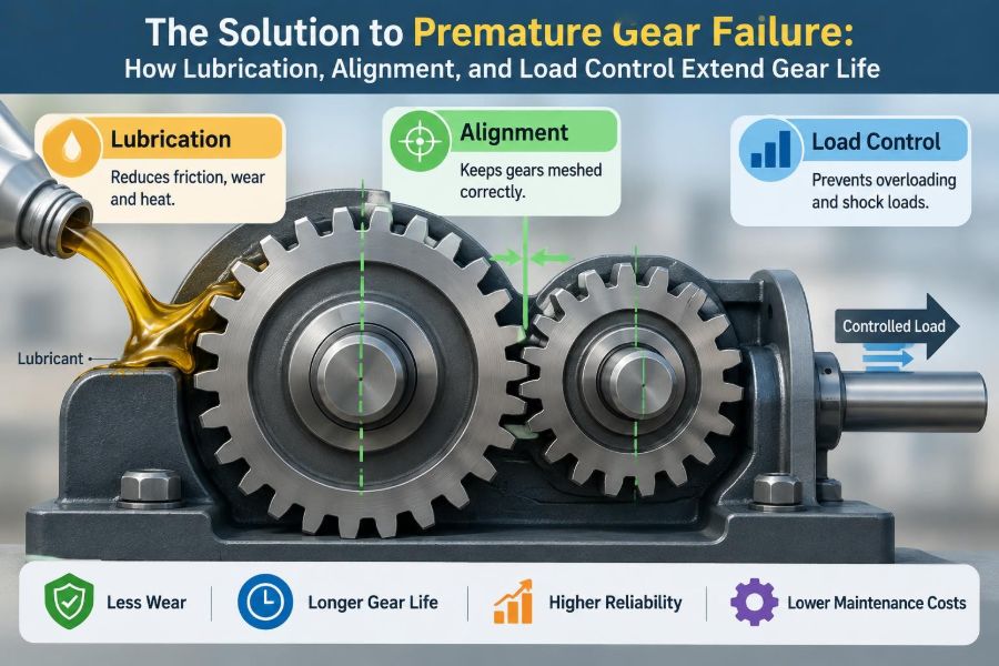
Extending gear life is not about finding one miracle oil or tightening every component harder. It is about controlling the conditions at the tooth contact. Lubrication, alignment, and load management work together to keep contact stresses, heat, and fatigue within a range the gear system can tolerate.
🔩 Why Gears Fail Earlier Than Expected
A gear can be correctly designed for its nominal torque and still fail early in service. Design calculations rely on assumptions about loading, material quality, lubrication, mounting stiffness, temperature, and duty cycle. When field conditions differ substantially, the expected life changes.
Premature failure usually means that damage accumulated faster than anticipated. A single overload can cause immediate damage, but many failures develop through repeated small events: inadequate oil film, minor misalignment, vibration, or frequent starts under load.
⚙️ The Tooth Contact Is Where the Story Begins
Meshing gear teeth transfer force through a small moving contact region. As teeth enter mesh, slide across one another, and leave mesh, the local pressure can be very high even when the gearbox appears modest in size.
The contact pattern should be distributed across an appropriate portion of the tooth face. When it becomes concentrated at one edge or near a tip, local stress rises sharply. That concentration is the common link between alignment problems, deflection, poor assembly, and many tooth failures.
🧠 Two Main Families of Gear Damage
Gear damage is often grouped into tooth bending fatigue and surface distress. Bending fatigue begins near the tooth root, where repeated loading can initiate a crack. Surface distress occurs at or near the flanks, where teeth roll and slide against each other.
Pitting, micropitting, scuffing, abrasive wear, corrosion, and plastic deformation are surface-related modes. More than one mode can appear in the same gearbox, so identifying the first damage mechanism matters more than simply replacing the visibly damaged part.
🔍 Reading the Evidence on Gear Teeth
Inspection patterns provide useful diagnostic clues. A broken tooth is dramatic, but its fracture surface and the condition of neighboring teeth may indicate whether the break resulted from fatigue, overload, poor material condition, or damage initiated by surface distress.
| Observed condition | Likely contributing conditions |
|---|---|
| Pitting across loaded flanks | Contact fatigue, insufficient film thickness, excessive load, or rough surfaces |
| Fine gray frosting or rippling | Micropitting, often associated with thin lubricant films and unfavorable surface conditions |
| Scored, smeared, or discolored flanks | Scuffing from film breakdown, high sliding speed, heat, or unsuitable oil |
| Wear concentrated at one face edge | Misalignment, shaft deflection, bearing clearance, or housing distortion |
| Crack or break near tooth root | Bending fatigue, stress concentration, overload, or an existing defect |
These patterns are clues, not final proof. A reliable diagnosis combines visual evidence with oil condition, temperature history, vibration data, loading records, and dimensional checks.
🛢️ Lubrication Does More Than Make Parts Slippery
Gear lubricant must separate surfaces where possible, reduce friction where separation is incomplete, carry heat away from the mesh, protect against corrosion, and transport contaminants toward filters or settling zones. It is part of the machine’s operating system, not a consumable chosen only by convenience.
In a healthy contact, an oil film carries much of the load. The film is not equally thick everywhere because gear teeth experience changing rolling and sliding conditions through the mesh cycle.
🌊 Understanding the Lubrication Regimes
At sufficiently favorable speed, viscosity, load, and surface condition, a full fluid film may separate most of the opposing asperities, the microscopic peaks on real surfaces. This is often called elastohydrodynamic lubrication, or EHL, because pressure elastically changes both the surfaces and lubricant behavior.
When the film becomes too thin, asperities interact more frequently. The contact enters mixed lubrication, where antiwear or extreme-pressure additives may help protect surfaces, but friction and damage risk increase. Boundary lubrication describes more direct surface interaction and is generally a harsher condition for loaded gears.
🧪 Selecting the Right Oil Viscosity
Viscosity is the lubricant’s resistance to flow. Higher viscosity can support a thicker separating film, but it also increases churning losses, may raise operating temperature, and can create poor flow during cold starts. Lower viscosity reduces drag but may not maintain an adequate film under load.
The correct grade depends on gear type, speed, load, operating temperature, lubrication method, and manufacturer guidance. Selecting oil solely by what is available in the maintenance store is a common route to avoidable wear.
🌡️ Temperature Changes the Lubrication Decision
Oil becomes less viscous as temperature rises. A lubricant that performs adequately at a moderate bulk oil temperature may provide a much thinner film when the gearbox runs hot during summer operation, sustained loading, or restricted cooling.
High temperature also accelerates oil oxidation and can shorten additive life. Low temperature brings a different risk: oil may circulate poorly at startup, leaving remote bearings and meshes insufficiently supplied until the system warms.
🧴 Additives Have a Specific Job
Industrial gear oils often contain additives for oxidation resistance, corrosion protection, foam control, demulsibility, and protection under high load. Extreme-pressure additives can form protective reaction layers under severe contact conditions, but they are not a substitute for correct viscosity, clean oil, or proper alignment.
Compatibility matters. The lubricant must suit the gear material, bearings, seals, and any yellow-metal components in the system. Mixing products without confirming compatibility can compromise additive balance and make oil-condition trends harder to interpret.
💧 Water Is a Small Contaminant With Large Consequences
Water can enter through damaged breathers, washdown exposure, condensation, or poorly sealed inspection covers. It promotes corrosion, reduces lubricant performance, contributes to additive depletion, and can interfere with the formation of a stable oil film.
Cloudy oil may indicate water contamination, although appearance alone is not enough to determine its amount or form. Finding the ingress path is essential; changing the oil without repairing the breather, seal, or cover simply restarts the problem.
🧹 Particle Control Protects Both Teeth and Bearings
Hard particles trapped between loaded teeth can scratch surfaces, disrupt the lubricant film, and create raised edges that worsen subsequent contact. Abrasive wear also generates more debris, creating a self-reinforcing cycle.
Effective particle control includes clean filling practices, appropriate filtration where the system supports it, sealed storage containers, clean breathers, and inspection of magnetic plugs or filters. The goal is not just cleaner-looking oil; it is lower abrasive damage at loaded contacts.
🫧 Foaming and Air Entrainment Reduce Film Reliability
Foam on the oil surface and air dispersed throughout the oil are related but different issues. Entrained air can reduce effective film strength, impair pump performance, increase oxidation, and make level readings unreliable.
Possible causes include incorrect oil level, return lines discharging above the oil surface, excessive agitation, unsuitable oil, or air leakage on the suction side of a circulating system. Treat persistent foam as a system symptom rather than a cosmetic issue.
📏 Alignment Is About the Entire Power Train
Alignment is often discussed as a motor-to-gearbox coupling task, but gear life depends on the position and stiffness of the whole drive train. Shaft centerlines, bearing locations, gear mounting faces, housing bores, and driven equipment all influence how load spreads across a gear face.
A coupling can be aligned accurately while an internal gear mesh remains poorly loaded because of shaft deflection, a worn bearing, or a distorted housing. Alignment must therefore be checked as a mechanical system, not as a single measurement.
🎯 What Misalignment Does to a Gear Mesh
Misalignment tilts or offsets the effective tooth contact. Instead of sharing load broadly, one side of the tooth face carries a disproportionate amount. This condition is often called edge loading.
Edge loading raises local contact stress and tooth-root stress at the same time. It can produce localized pitting, wear bands near one face edge, elevated vibration, and heat. A gear may continue operating for some time, but the damage rate is no longer evenly distributed.
🏗️ Soft Foot and Baseplate Distortion
Soft foot occurs when one machine foot does not sit flat on its mounting surface. Tightening the hold-down bolts forces the machine casing to deform, changing shaft position and potentially introducing alignment error that was not present when bolts were loose.
Baseplates can also distort because of poor support, thermal growth, corrosion, or structural flexibility. Before making fine alignment corrections, technicians should confirm that mounting surfaces are clean, fasteners are tightened correctly, and the machine is supported as intended.
🌡️ Thermal Growth Can Undo Cold Alignment
Motors, gearboxes, pumps, and driven shafts do not all heat at the same rate or reach the same temperature. Their centerlines can move during operation. A drive aligned perfectly at ambient temperature may become offset at normal load.
Where thermal movement is meaningful, alignment targets may include calculated or measured cold offsets. The correct target depends on the actual machine arrangement and temperatures, so generic compensation values should not be copied blindly.
🪛 Bearings and Clearances Shape Tooth Contact
Bearings locate shafts and resist the forces generated by gears. Wear, incorrect preload, excessive internal clearance, damaged races, or loose fits allow a shaft to move. That movement changes backlash and contact position while the gearbox is loaded.
Replacing damaged gears without examining bearing condition can lead to repeat failures. In helical and bevel gear sets especially, axial forces make bearing support and adjustment central to maintaining the intended mesh geometry.
📐 Backlash Is Necessary, but Not Arbitrary
Backlash is the intentional clearance between mating teeth measured along the pitch circle. It provides room for lubrication, manufacturing variation, thermal expansion, and mounting tolerance. Too little backlash can cause binding and heat; too much can increase impact, noise, and reversal shock.
Acceptable backlash depends on the gear design and manufacturer specifications. A value that looks reasonable on one gearbox can be incorrect on another, especially when gear size, tooth form, operating temperature, and service conditions differ.
🖍️ Contact Pattern Checks Reveal Load Distribution
Marking compound applied to teeth can reveal the approximate contact pattern under a light turning load. It is a valuable assembly and troubleshooting check because it makes face-width and profile contact visible.
However, a no-load pattern is not the same as an operating pattern. Shaft deflection, housing flexibility, and thermal effects can move contact under torque. Use marking as one piece of evidence alongside loaded measurements and inspection history.
🏋️ Load Control Starts With Knowing the Duty Cycle
A gearbox is affected not only by peak torque but by how long it operates at each load. Continuous moderate loading, intermittent high loading, frequent reversals, and repeated starts can produce very different fatigue and thermal conditions even if average power appears similar.
Documenting the real duty cycle helps expose hidden mismatch between the gearbox selection and the application. It also helps maintenance teams distinguish a lubrication problem from a machine that is simply being asked to transmit more demanding loads than intended.
💥 Shock Loads Leave a Different Kind of Damage
Shock loads arise from sudden starts, jams, impacts, rapid direction changes, and driven equipment that cyclically resists motion. A conveyor catching material or a crusher encountering a hard inclusion can transmit torque far above steady running demand.
Severe events may plastically deform tooth surfaces, crack roots, damage couplings, or brinell bearing races. Less dramatic shocks can gradually initiate fatigue cracks. Torque limiters, controlled acceleration, compliant couplings, and process interlocks can reduce exposure when properly selected.
🔄 Reversing Service Deserves Extra Attention
In reversing drives, the loaded flanks alternate. Clearance is taken up repeatedly, and torque transitions can create impact if backlash, coupling condition, or control tuning is poor. Hoists, indexing systems, rolling equipment, and positioning axes often face this challenge.
These systems benefit from careful review of acceleration and deceleration profiles. Reducing abrupt torque reversals can protect gears, but it must be balanced against process requirements, stopping accuracy, and safety functions.
📉 Underload Can Also Create Problems
Not every damaging condition is an overload. Very lightly loaded gears may run in unfavorable contact conditions, particularly where surface finish, speed, oil viscosity, and geometry make it difficult to establish a robust film. Light load can also allow vibration or rattle in systems with clearance.
This does not mean a gearbox should be deliberately overloaded. It means selection and operating conditions should be evaluated across the expected load range rather than only at maximum torque.
🧮 Service Factors Are Screening Tools, Not Guarantees
Service factors adjust a nominal rating to account for application severity. They are useful for preliminary selection because they acknowledge that a smooth fan drive and a reversing mixer do not impose the same demands.
But a service factor cannot capture every installation detail. Misalignment, contamination, unusual temperature, transient torque, and structural flexibility can still dominate field performance. Treat rating methods as a foundation, then validate the actual machine behavior.
👂 Condition Monitoring Finds Change Before Failure
Trend-based monitoring is more useful than a single isolated reading. Changes in vibration, oil debris, temperature, noise, or motor current can signal developing trouble before a gearbox reaches a failure point.
- Vibration analysis can identify changes related to mesh frequency, bearings, looseness, and imbalance.
- Oil analysis can track viscosity, contamination, water, oxidation indicators, and wear debris.
- Temperature trending can reveal increased friction, low oil level, cooling problems, or overload.
- Visual inspection can detect leaks, breather blockage, mounting issues, and abnormal tooth patterns.
Interpretation requires context. A vibration increase does not automatically identify one failed component, and oil results should be compared with the lubricant type, sampling method, and prior trend.
🧫 Oil Sampling Must Represent the Machine
An oil sample taken from a stagnant drain plug may not represent oil circulating through the gears and bearings. When possible, sample from a live zone or a dedicated port while the machine is operating safely or shortly after shutdown, following the site procedure.
Use clean bottles and consistent sampling locations. Poor sampling technique can introduce debris or water and create misleading results that send a maintenance team toward the wrong conclusion.
🔧 A Practical Inspection Routine
Routine checks do not need to be complicated, but they should be consistent. The interval should reflect the gearbox criticality, environment, load severity, and consequence of failure.
- Check oil level, leakage, breather condition, and abnormal external heating.
- Listen for changes in gear noise, impacts, or cyclic rumble.
- Review operating load, starts, trips, jams, and process changes.
- Trend vibration and oil condition where the asset justifies it.
- Inspect accessible teeth, couplings, fasteners, and foundations during planned outages.
- Record findings clearly enough that the next inspection can identify change.
🚫 Maintenance Practices That Shorten Gear Life
Several well-intended practices create risk: topping up with an unverified oil, overfilling a splash-lubricated housing, washing around unprotected breathers, ignoring a recurring seal leak, or replacing gears without correcting the cause of their damage.
Another common mistake is adjusting alignment only after a coupling fails. By then, the underlying baseplate movement, soft foot, bearing wear, or thermal shift may have affected the gears for a long period.
🧰 When a Gearbox Is Rebuilt
A rebuild is an opportunity to restore geometry, not merely exchange damaged components. Inspect shafts, keys, splines, bearing seats, housing bores, gear mounting faces, and lubrication passages. A new gear mounted on a worn shaft or supported by a loose bearing fit may inherit the same loading problem.
Record backlash, bearing settings, tooth contact observations, component identification, and lubricant used. These details help verify the rebuild and provide a baseline if symptoms return.
🧩 Designing for Maintainability
Good reliability begins in design choices that make correct maintenance practical. Accessible fill, drain, level, and sampling points reduce contamination risk. Sight glasses, magnetic plugs, filter indicators, and properly sized breathers can make degradation easier to detect.
Rigid but serviceable mounting, provisions for alignment measurement, and adequate space around couplings also matter. A gearbox that is difficult to inspect is more likely to run with small problems until they become expensive repairs.
🤝 Treat Lubrication, Alignment, and Load as One System
These three controls are connected. Misalignment concentrates load, which thins the effective lubricant film and raises temperature. Elevated temperature lowers viscosity, which can accelerate surface distress. Surface damage then increases friction and debris, worsening the condition further.
Likewise, a load spike may not cause immediate breakage in a well-aligned, well-lubricated system, but it becomes more damaging when the contact is already edge-loaded or contaminated. Root-cause work should therefore resist single-cause explanations unless the evidence is clear.
✅ The Core Principle for Longer Gear Life
Long gear life comes from keeping force distributed, surfaces separated, and operating demands controlled. The practical priorities are straightforward: use and maintain the correct lubricant, keep it clean and at a suitable temperature, preserve shaft and housing alignment, support shafts correctly, and understand real torque events.
When a gearbox shows distress, begin with evidence rather than assumptions. Examine the damage pattern, verify lubrication condition and delivery, assess alignment and support stiffness, and compare actual loading with the machine’s intended duty. This approach turns a repair from a repeating expense into a reliability improvement.
Gears last longer when the system consistently gives each tooth a clean lubricant film, a stable contact pattern, and a load it was designed to carry. ⚙️🛢️📐