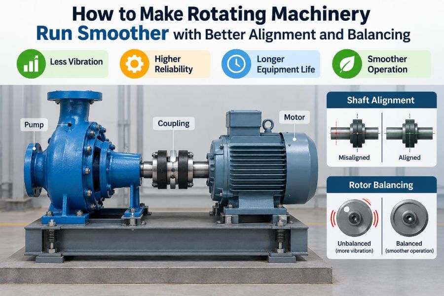

A pump begins to hum more loudly than usual. A fan develops a vibration that can be felt through the handrail. A motor bearing that was replaced only months ago is already running hot.
These problems are often treated as separate failures: a bad bearing, a loose base, an overloaded coupling, or an unreliable machine. Yet many begin with two conditions that are easy to underestimate—shaft misalignment and rotor unbalance.
Rotating equipment does not need to be visibly shaking to be under stress. Small geometric errors can create repeating forces thousands of times per minute, steadily loading bearings, seals, couplings, supports, and connected pipework.
Better alignment and balancing do not make every machine problem disappear. They do, however, remove two common sources of avoidable vibration and give machinery a much better chance of operating smoothly, efficiently, and predictably.
🔄 The Meaning of Smooth Rotation
A smoothly running machine has more than low vibration. Its rotating parts follow their intended centerlines, its forces are distributed predictably, and its components operate within their design limits.
In a motor-pump set, the motor shaft, coupling, and pump shaft should rotate as one functional train. The shafts do not need to be physically continuous, but their relationship must be controlled. When it is not, the coupling and bearings are forced to accommodate motion they were not meant to carry continuously.
🧭 Alignment and Balancing Are Different Jobs
Alignment concerns the geometric relationship between connected shaft centerlines. Balancing concerns the distribution of mass around a rotating axis.
A perfectly balanced fan can still shake because its shaft is misaligned with the motor. Likewise, a carefully aligned motor and pump can vibrate because the pump impeller or fan wheel has an uneven mass distribution. Effective maintenance distinguishes the two rather than using one correction to compensate for the other.
⚙️ Why Small Errors Create Large Effects
Rotational speed magnifies defects. An off-center mass creates centrifugal force, and that force rises rapidly as speed increases. A small amount of eccentricity that seems harmless when a rotor is turned by hand may become significant at operating speed.
Misalignment is similarly repetitive. Every revolution bends or deflects connected components slightly, creating cyclic loading. Repetition is the key issue: a modest force applied once may be harmless, while the same force applied for millions of cycles can shorten component life.
📉 The Cost of Letting Vibration Continue
Excess vibration does not always cause an immediate shutdown. More often, it gradually increases wear and makes the machine harder to diagnose. Bearings may develop damage, seals may leak, fasteners may loosen, and electrical connections or instrumentation may be affected.
There is also an energy penalty. A machine fighting internal forces uses some of its input energy to flex shafts, heat bearings, and excite structural vibration instead of doing useful work. The exact loss depends on the machine and defect, but the operating principle is straightforward.
🏗️ Start with a Stable Mechanical Foundation
Alignment measurements are only meaningful if the machine supports are sound. A distorted baseplate, loose anchor bolts, cracked grout, or weak structural frame can change the machine position as loads vary.
Before precision work begins, inspect the foundation, baseplate, hold-down bolts, and mounting surfaces. Correct obvious structural issues first. Attempting to align machinery on an unstable base is like leveling a table while someone is bending its legs.
🦶 Understand Soft Foot Before Moving Machines
Soft foot exists when one or more machine feet do not sit flat on the mounting surface. Tightening the hold-down bolt pulls the machine frame into distortion, which can alter shaft position and create internal stress.
It can result from warped feet, dirt or burrs under a foot, uneven base surfaces, incorrect shims, or excessive stacked shims. Soft foot should be checked and corrected before final shaft alignment, because tightening the machine afterward may undo the result.
🧹 Cleanliness Is a Precision Requirement
A thin layer of corrosion, paint, oil residue, or grit can change a machine’s position. This matters because alignment corrections are often made in very small increments.
Clean the feet, shim packs, baseplate pads, and bolt threads. Use shims that are clean, flat, and appropriate for machinery alignment. A carefully calculated correction is of little value if a hidden burr under a foot moves the machine when the bolts are tightened.
📐 What Shaft Misalignment Looks Like
Misalignment is commonly described as either offset or angular, although real machines often have both at the same time. The condition may exist in the vertical plane, horizontal plane, or both.
| Condition | What it means | Typical correction |
|---|---|---|
| Offset, or parallel, misalignment | Centerlines are parallel but separated | Move the machine sideways or vertically |
| Angular misalignment | Centerlines meet at an angle | Change relative position at machine feet |
| Combined misalignment | Both centerline separation and angle are present | Use calculated vertical and horizontal moves |
Flexible couplings tolerate some error, but tolerance is not an invitation to ignore alignment. Their flexibility is intended to accommodate limited movement and normal operating effects, not to conceal a poor installation.
↔️ Parallel Offset: Centerlines That Miss
Parallel offset occurs when two shafts point in the same direction but rotate around different centerlines. Imagine two straight pencils lying side by side: they are parallel, yet their axes do not coincide.
This condition makes the coupling flex once per revolution. Depending on the coupling and machine arrangement, it can increase bearing loading and produce vibration patterns related to running speed.
📐 Angular Error: Shafts Pointing Apart
Angular misalignment occurs when shaft centerlines are not parallel. The shafts may appear to meet near the coupling, but their axes diverge away from it.
Angular error can create axial forces as well as radial forces. That distinction matters because many bearings and seals have limited ability to absorb continuous thrust or shaft movement in directions outside their intended duty.
🌡️ Consider Thermal Growth at Operating Temperature
Machines change position as they heat. A hot pump casing, turbine, compressor, or motor may expand differently from its driver or support structure. If alignment is set only for the cold condition, it may be less accurate during normal operation.
Thermal growth targets are planned cold-position offsets intended to bring shafts closer to alignment at operating temperature. They should be based on machine information, operating conditions, and sound engineering judgment—not guessed from a general rule.
🧪 Check for Process Forces Before Final Alignment
Pipe strain can move a pump when piping is connected. Belt tension, gearbox reaction forces, ductwork loads, and electrical conduit can have similar effects. A machine that aligns well when disconnected may shift after the system is assembled.
Where practical, compare machine position before and after connecting piping or other external elements. If the machine moves, solve the external loading problem rather than forcing alignment by moving the machine against the load.
🔍 Recognize Common Alignment Symptoms
No single symptom proves misalignment, but several clues justify investigation. Watch for recurring coupling element wear, frequent bearing problems, hot bearing housings, seal failures, unusual axial vibration, or a machine that changes vibration noticeably after alignment work.
Symptoms must be interpreted in context. Similar signs can arise from imbalance, looseness, resonance, bearing defects, hydraulic instability, or electrical faults. Vibration data is valuable, but it should support a mechanical inspection rather than replace it.
📏 Choose a Measurement Method That Fits the Work
A straightedge and feeler gauges can reveal gross angular error on some simple installations. Rim-and-face dial indicator methods can provide useful measurements when performed carefully. Laser shaft alignment systems generally make it easier to measure both planes, calculate corrections, and document results.
The instrument is not the whole method. Good results depend on trained setup, correct dimensions, stable brackets, shaft rotation, valid readings, and disciplined machine moves. A sophisticated tool cannot compensate for dirty feet, loose bolts, or an incorrect setup.
🎯 Prepare Before Taking Alignment Readings
Lock out the equipment according to site procedures before working around couplings or rotating shafts. Remove coupling guards only when authorized, inspect the coupling, and verify that shafts can be rotated safely by the approved method.
- Confirm the base and hold-down bolts are secure.
- Correct soft foot and clean all mounting surfaces.
- Record machine dimensions accurately.
- Check for visible coupling damage and excessive shaft runout.
- Identify whether thermal targets or intentional offsets apply.
This preparation reduces false readings and prevents repeated, unplanned correction cycles.
🧮 Read the Numbers, Not Just the Screen Color
Alignment systems may display a pass or fail result, but the underlying values matter. Understand whether the reported error is angularity, offset, coupling-plane condition, or correction required at each foot.
Also compare results with the machine’s speed, coupling type, manufacturer guidance, and site acceptance criteria. A generic tolerance chart can be a useful starting point, but critical machines or unusual operating conditions may require more conservative targets.
🔧 Make Controlled Vertical Corrections
Vertical alignment changes are usually made by adding or removing shims beneath machine feet. Make corrections systematically, keeping shim packs thin, clean, and manageable.
A common mistake is adding many thin shims until the desired number appears on the instrument. Large shim stacks can settle, corrode, or introduce instability. Where a substantial adjustment is necessary, investigate whether the baseplate or mounting arrangement needs more fundamental correction.
➡️ Move Machines Horizontally Without Damage
Horizontal corrections should use controlled, repeatable movement. Jacking bolts are ideal when the baseplate provides them. If they are absent, suitable pushing hardware or carefully planned methods may be used under site procedures.
Do not strike machine feet casually with a hammer. Impact can damage components, disturb instruments, create unpredictable movement, or lead to unsafe practices. After every move, re-tighten as required and remeasure rather than assuming the correction was exact.
🔩 Tighten Bolts in a Repeatable Sequence
A machine can shift while hold-down bolts are tightened. Tighten in a planned sequence and observe whether readings change. If they do, determine whether soft foot, poor contact, bolt condition, or base distortion is contributing.
The final reading should be taken with the machine secured in its actual operating mounting condition. An alignment result measured with loose bolts is not a finished result.
🌀 What Rotor Unbalance Really Means
A rotor is unbalanced when its mass center does not lie on its intended rotation axis. As it spins, the displaced mass produces a rotating force that is transmitted through the shaft, bearings, and structure.
Common examples include fan wheels with built-up dirt, pump impellers with deposits or damage, grinding wheels, motor rotors, turbine components, and belt-driven pulleys. Unbalance can develop after installation; it is not limited to manufacturing defects.
🧩 Static and Couple Unbalance
Static unbalance can be understood as a heavy spot on a narrow rotor. If placed on low-friction supports, the heavy point tends to rotate downward. A single correction plane may be enough for this kind of condition.
Couple unbalance involves unequal mass distribution at different axial locations. It may not reveal itself as a simple heavy spot, yet it creates a rocking tendency while rotating. Longer rotors frequently require two-plane balancing to address both effects.
🧼 Deposits Can Undo a Good Balance
Fans handling dusty air, mixers processing sticky material, and pumps moving contaminated liquids can accumulate deposits unevenly. Corrosion, erosion, missing hardware, cracked blades, and repairs can also change mass distribution.
Cleaning a rotor may improve vibration, but do not assume cleaning alone resolves the issue. Inspect for blade damage, uneven wear, loose parts, and dimensional changes. A rotor with a structural defect needs repair or replacement decisions based on its service and safety requirements.
📊 The Vibration Clue for Unbalance
Unbalance often produces vibration strongly related to shaft running speed, commonly called a 1× running-speed component. The response is often mainly radial, but machine structure, bearing type, and measurement location influence what is observed.
This pattern is a clue, not a verdict. Misalignment, looseness, bent shafts, eccentric pulleys, hydraulic forces, and resonance can also produce running-speed vibration. Reliable diagnosis combines vibration measurements with physical inspection and process knowledge.
🏭 In-Shop Balancing Versus Field Balancing
Shop balancing is performed on a balancing machine, typically before installation or after rotor removal. It provides a controlled environment and is often the preferred approach for accessible rotors undergoing repair.
Field balancing adjusts a rotor in its installed machine using measured vibration and phase information. It can be practical when rotor removal is difficult, but it requires appropriate instrumentation, safe access, stable operating conditions, and personnel who understand the method.
🧷 Correction Weights Need Engineering Discipline
Balancing corrections may remove material, add weight, or reposition existing adjustable weights. Any method must preserve rotor integrity and prevent the correction from becoming a loose projectile.
Never add an improvised weight without considering attachment security, clearance, fatigue, corrosion, temperature, and rotor speed. Manufacturer-approved balancing locations and repair procedures are especially important for high-speed or safety-critical equipment.
📈 Balance Quality Depends on the Application
Not every rotor needs the same balance quality. Acceptable residual unbalance depends on rotor mass, speed, geometry, bearing arrangement, machine purpose, and consequences of vibration.
A small high-speed rotor may need much tighter control than a slow, rugged agricultural fan. Conversely, demanding an unnecessarily fine balance can add cost without meaningful operational benefit. The target should match the machine’s design and service requirements.
🎵 Avoid Confusing Unbalance with Resonance
Resonance occurs when a forcing frequency approaches a natural frequency of the machine, support, or connected structure. Even a modest unbalance force can then create large vibration because the structure responds strongly.
Adding balance weights may reduce the forcing force, but it cannot always solve a resonance problem. Structural stiffness, support conditions, speed range, piping, and machine design may need review. Changing operating speed can sometimes move the system away from a troublesome range, but only if process and equipment limits permit it.
🛢️ Bearings, Lubrication, and Alignment Interact
Alignment does not replace proper lubrication, and lubrication does not cure misalignment. Poor alignment can overload bearings; contaminated or incorrect lubricant can damage them even when alignment is excellent.
When bearing failures recur, avoid single-cause thinking. Review lubrication type and quantity, contamination control, installation technique, housing fits, shaft condition, alignment, balance, electrical effects where relevant, and the actual operating load.
🔗 Couplings Are Not Vibration Bandages
Flexible couplings are selected to transmit torque while accommodating specified movement. Different designs handle angular, parallel, axial, and torsional behavior differently. Their ratings and limits should be treated as design constraints.
Using a more flexible coupling to hide serious misalignment can transfer the problem elsewhere. The coupling may wear faster, while bearings and seals continue to experience undesirable forces. Choose the coupling for the application, then align within the manufacturer’s recommendations.
🧾 Document the Condition You Found
Alignment and balancing work becomes more valuable when it creates a usable maintenance record. Record as-found and as-left readings, soft-foot observations, shim changes, thermal targets, coupling condition, vibration values, and any unresolved concerns.
Trend records help teams distinguish a one-time installation problem from a machine that drifts over time. They also make future troubleshooting faster because technicians can compare current conditions with a known baseline.
🗓️ Build Alignment into the Maintenance Plan
Precision alignment is most effective when planned at the right moments: installation, major overhaul, motor replacement, coupling replacement, baseplate repair, repeated seal or bearing failures, and after events that may have shifted equipment.
Routine vibration monitoring can help decide when further investigation is justified. The goal is not to align every machine constantly, but to use condition information and maintenance opportunities intelligently.
⚠️ Common Mistakes That Waste Good Work
Several habits repeatedly produce disappointing results:
- Aligning before correcting soft foot.
- Ignoring pipe strain or external loads.
- Using worn, damaged, or poorly installed coupling components.
- Taking readings with loose hardware or unstable brackets.
- Forgetting thermal growth on machines that run significantly hotter than ambient.
- Balancing a dirty, damaged rotor without first restoring its condition.
- Treating one vibration reading as a complete diagnosis.
The pattern behind these mistakes is simple: precision measurement cannot compensate for an uncontrolled mechanical system.
🦺 Safety Must Shape the Entire Task
Alignment and balancing involve pinch points, suspended components, energized equipment, rotating shafts, and sometimes trial weights or high temperatures. Follow site isolation procedures, guarding requirements, lifting practices, and machine-specific instructions.
Field balancing deserves particular caution because measurements are taken while equipment operates. Use suitable instruments and access arrangements, keep clear of rotating parts, and stop the work if conditions are unstable or unsafe. When capability is uncertain, involve qualified vibration and reliability personnel.
🧠 A Practical Troubleshooting Sequence
When a rotating machine runs rough, begin broadly and narrow the diagnosis with evidence. A useful sequence is:
- Verify safe operating conditions and inspect for obvious looseness, rubbing, leaks, or damage.
- Review recent changes, repairs, process conditions, and vibration history.
- Check foundation condition, fasteners, soft foot, coupling condition, and external loads.
- Measure alignment after correcting mounting problems.
- Evaluate rotor cleanliness, damage, runout, and evidence of unbalance.
- Consider resonance, bearing condition, hydraulic or aerodynamic forces, and electrical issues.
- Document the correction and confirm the result under representative operation.
This order avoids the temptation to balance or align first simply because those tasks are familiar.
🏁 The Core Principle: Control Forces at Their Source
Better alignment places connected shafts in the relationship the machine was designed to use. Better balancing places rotor mass around the axis it was designed to rotate about. Together, they reduce unnecessary cyclic forces before those forces become heat, noise, wear, and vibration.
The strongest results come from treating alignment and balancing as parts of a larger mechanical system. Stable foundations, clean mounting surfaces, correct assembly, realistic operating conditions, suitable tolerances, and verification after the work all matter.
When a machine is smooth, do not assume it will stay that way forever. Preserve the condition with inspection, condition monitoring, careful repairs, and records that allow the next technician to understand what changed.
Smoother rotating machinery is rarely the result of one adjustment; it is the result of controlling geometry, mass, support, and operating forces with care. ⚙️📈🛠️