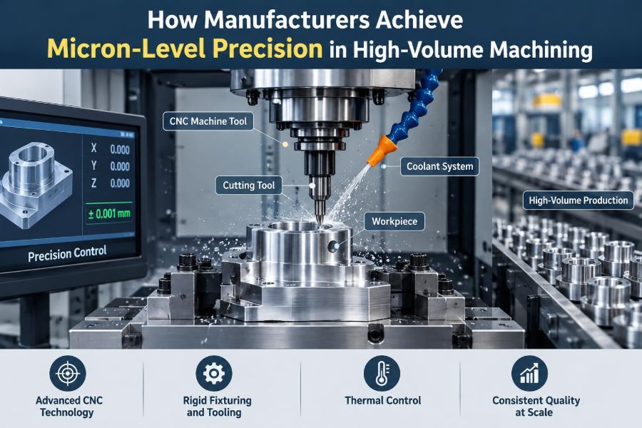

A fuel-injection component, orthopedic screw, camera-lens barrel, or electric-motor shaft may look like a simple metal part. Yet a small error in diameter, roundness, or position can turn a smooth assembly into one that leaks, vibrates, binds, or wears early.
Making one accurate part in a carefully controlled machine shop is challenging. Making hundreds of thousands of accurate parts—across multiple shifts, tool changes, material batches, and operators—is a different engineering problem altogether.
That is where micron-level machining enters the picture. A micron, or micrometre, is one millionth of a metre. For perspective, it is far smaller than the width of a human hair. Not every feature needs this level of control, but the features that govern sealing, bearing fits, motion, and interchangeability often do.
High-volume precision does not come from buying a single “accurate” machine. It comes from designing a production system in which machines, tools, materials, measurement, data, and people continuously control variation.
🎯 What Micron-Level Precision Actually Means
Micron-level precision is often used loosely. In production, it may refer to holding a dimensional tolerance measured in microns, maintaining low variation around a target size, achieving a fine form tolerance, or controlling the relationship between features.
A part can meet its diameter tolerance and still fail its functional purpose. For example, a bore may be the correct average size but be tapered, out-of-round, or misaligned with another bore. Precision therefore includes size, form, orientation, position, and surface condition.
📏 Tolerance Is Not the Same as Accuracy
Tolerance is the permitted range defined by the drawing. Accuracy describes closeness to the intended value. Repeatability describes how consistently a process returns to the same result, while reproducibility concerns consistency across operators, machines, or measurement conditions.
A stable process can repeatedly produce a diameter slightly away from nominal. That is repeatable but not well centered. Manufacturers aim to center the process within the tolerance band so normal variation has room to occur without producing rejects.
⚙️ Why Volume Makes the Problem Harder
At high volume, small influences accumulate. A cutting edge wears gradually, coolant warms, a fixture collects chips, material hardness shifts between lots, and machine components expand after startup.
Production engineering must anticipate these changes rather than react after defects appear. The goal is not a perfect first part; it is a process that remains capable for a long run and signals when it begins to drift.
🧩 Start With Functional Requirements
Reliable precision begins before machining. Designers should identify which dimensions truly control function: a bearing seat, a sealing land, a coaxial bore pair, or a locating face. Those features deserve the tightest control and the clearest datum strategy.
Overly tight tolerances on nonfunctional features raise cost, slow cycle time, and complicate inspection without improving the assembly. Conversely, a poorly specified datum can make a critical positional requirement difficult to manufacture and inspect consistently.
🗺️ Build a Sensible Datum Scheme
A datum is a theoretically exact reference used to locate and orient a part. In practice, manufacturers must establish it through fixture contacts, probes, or measured surfaces. The part should be located in a way that resembles how it functions in its final assembly whenever practical.
Consider a housing that bolts to a mating component. If the bolt face and pilot bore establish its assembly location, using those features as manufacturing and inspection references reduces ambiguity. Changing references between operations introduces opportunities for stack-up error.
🏗️ Choose a Machine for the Whole Process
Machine-tool selection is about more than catalog positioning accuracy. A high-volume cell needs sufficient structural stiffness, thermal behavior, spindle performance, axis dynamics, automation compatibility, and maintainability for the workpiece and cycle time.
A light, fast machine may suit small aluminum components but struggle with an interrupted steel cut. A very rigid machine can be excellent for hard turning but unnecessarily costly for a low-load process. The machine must match the cutting physics, not simply the tolerance on the drawing.
🧱 Stiffness Prevents Deflection Errors
Every cutting force tries to bend something: the tool, holder, spindle, fixture, workpiece, or machine structure. Deflection changes the actual tool-to-part position while cutting, so the programmed path no longer creates the intended geometry.
Shorter tool overhang, robust holders, well-supported parts, and sensible cutting loads all reduce this effect. Thin-walled components are especially demanding because removing material can release internal stress and make the workpiece distort after unclamping.
🌡️ Thermal Stability Is a Hidden Dimension
Metal expands as temperature changes. So do machine ballscrews, spindle housings, fixtures, probes, and the part itself. A component measured immediately after a heat-generating operation may not read the same after reaching inspection-room temperature.
Manufacturers manage thermal effects with warm-up routines, temperature-controlled coolant, enclosure control, stable process schedules, machine compensation models, and measurement practices that account for part temperature. Thermal control is not optional when tolerances become very small.
🔩 Fixtures Must Locate, Not Merely Hold
A fixture has two jobs: accurately locate the part and resist cutting forces without distorting it. Clamping alone does not guarantee either. If a part can settle differently against a locator from one cycle to the next, the process may show unexplained positional variation.
Good fixtures use defined locating points, chip-resistant contact areas, repeatable clamping, and enough support near cutting loads. They also permit loading and unloading without forcing operators or robots to fight the workholding.
🧲 Control Clamping Distortion
More clamp force is not automatically better. Excess force can deform a thin ring, tube, casting, or plastic component during machining. When the clamp releases, the part springs back and the finished feature is no longer where it was cut.
Engineers may use soft jaws shaped to the part, expanding mandrels, hydraulic fixtures, compliant supports, or staged operations. The right approach depends on geometry and material, but the principle is consistent: hold the work securely with the least distortion needed.
🛠️ Tooling Is a Consumable Precision System
Cutting tools are not fixed geometric objects. Edge wear, built-up edge, chipping, runout, coating condition, and tool seating all affect the cut. A tool that still “cuts” may already be producing unacceptable size or surface variation.
High-volume lines define tool-life limits from observed process behavior, not only from catastrophic failure. Tool offsets are adjusted in controlled increments, and replacement intervals are planned so tool changes occur before quality escapes become likely.
🌀 Runout Can Consume a Tight Tolerance
Runout is the radial movement seen when a rotating tool or workpiece does not turn perfectly about its intended axis. It can come from a spindle, collet, toolholder taper, dirty seating surface, bent tool, or part-gripping method.
In drilling and reaming, runout can enlarge or distort a hole. In milling, it makes one flute remove more material than another, accelerating uneven wear. Clean interfaces, qualified holders, proper tightening, and routine checks protect the available tolerance.
💧 Coolant Does More Than Keep Things Wet
Cutting fluid can remove heat, lubricate the cutting zone, evacuate chips, and improve surface finish. The correct method depends on the material and operation: some processes need directed high-pressure delivery, while others require controlled flow to avoid recutting chips.
Coolant concentration, cleanliness, temperature, and nozzle placement all matter. A nozzle bumped during maintenance may alter chip flow enough to cause scratches, insert damage, or inconsistent dimensions long before anyone notices an obvious problem.
🪵 Material Variation Enters the Machine
Even material supplied to the same specification can vary in hardness, microstructure, straightness, residual stress, and surface condition. Castings and forged blanks may also vary in stock allowance, which changes the cutting load from part to part.
Manufacturers control this through incoming checks, supplier requirements, lot traceability, machining allowances, and process settings robust enough to tolerate expected variation. A highly optimized program that works only on one ideal material batch is not a production-ready process.
🔄 Sequence Operations to Protect Datums
The order of operations determines what references are available and when stresses are released. A common strategy is to create stable locating surfaces early, perform roughing before finishing, and machine critical features when the part has adequate support.
For example, a part may be rough machined, allowed to stabilize if needed, then finish machined from the datums created in the first operation. The exact sequence varies, but preserving reference integrity is central to dimensional control.
✂️ Separate Roughing From Finishing
Roughing removes material efficiently and generates comparatively high forces and heat. Finishing removes a small, controlled allowance to achieve the final size, form, and surface quality. Asking one pass to do both jobs often makes the result sensitive to changing conditions.
This separation is particularly useful when roughing changes part temperature or releases stress. The finish pass can then be designed around predictable engagement, stable tool load, and a consistent remaining allowance.
🧠 Program for Stable Cutting Conditions
A capable CNC program avoids sudden engagement changes where possible. Smooth toolpaths, suitable entry and exit moves, constant-engagement milling strategies, and realistic acceleration settings reduce force spikes that mark surfaces or deflect tools.
Programming also includes practical details: safe retracts, chip-clearance moves, tool orientation, and compensation logic. A nominally correct CAM path can still create unstable machining if it ignores the rigidity of a long tool or delicate workpiece.
📐 Use the Right Finishing Process
Turning and milling can achieve excellent results, but they are not the answer to every requirement. Grinding is often chosen for hard materials, fine size control, and demanding form or finish. Honing can improve bore geometry and surface texture, while lapping may serve extremely fine flatness or sealing needs.
Secondary finishing adds cost, time, and handling risk. It should be selected because it provides a functional advantage that machining alone cannot reliably deliver, not because it appears more precise by default.
🔍 Measure Features, Not Just Parts
Inspection must target the characteristics that matter. A caliper is useful for many external dimensions but cannot establish roundness, cylindricity, or true position. A bore gauge, air gauge, vision system, coordinate measuring machine, or dedicated functional gauge may be more appropriate.
The measurement method also needs adequate resolution and stability relative to the tolerance. A system cannot confidently distinguish small process changes if its own variation is of similar magnitude to the changes being investigated.
🧪 Verify the Measurement System First
Before acting on measurement data, manufacturers evaluate whether the gauge and method are fit for purpose. This includes calibration, repeatability, reproducibility, fixture effects, operator technique, part cleanliness, and environmental sensitivity.
A misleading gauge creates expensive confusion. Operators may adjust a healthy process to chase measurement noise, making actual production worse. Measurement-system capability is part of process capability, not a separate administrative task.
📊 Use Statistical Process Control Wisely
Statistical process control, or SPC, uses repeated measurements plotted over time to distinguish routine variation from unusual signals. Control charts help teams notice a shift, trend, or increased spread before parts cross a specification limit.
SPC is not a substitute for understanding the process. A chart alone does not identify whether a trend came from wear, temperature, clamping, material, or a gauge issue. Its value lies in prompting timely investigation based on evidence.
🎯 Center the Process, Then Watch Its Spread
Capability indices are commonly used to compare process variation and centering with a tolerance band. The details of which index is appropriate depend on assumptions, sampling, and whether the process is stable, so a single value should never be interpreted in isolation.
Practically, teams ask two questions: Is the average close enough to the target? Is the natural spread small enough to remain safely within limits? A process crowded near one specification limit is vulnerable even if recent samples are acceptable.
🤖 Automation Improves Consistency—With Conditions
Robots, gantries, pallet systems, bar feeders, and automatic tool changers reduce handling variation and support unattended production. They can also ensure a repeatable loading sequence that would be difficult to sustain manually over long shifts.
Automation introduces its own risks: gripper wear, incorrect seating, sensor faults, mixed parts, and error recovery after interruptions. Automated cells need confirmation steps, robust part-present checks, controlled restart logic, and maintenance just as much as they need speed.
👁️ In-Process Gauging Closes the Loop
In-process gauging measures a feature during or immediately after machining, sometimes inside the machine or at an adjacent station. The result can trigger a controlled tool-offset correction, divert a suspect part, or alert an operator to drift.
This is especially effective for predictable changes such as gradual tool wear. It is less effective when the measured surface is hot, dirty, poorly accessible, or influenced by unstable clamping. The correction strategy must be validated so it does not overreact to noise.
🧹 Chips and Cleanliness Are Quality Variables
A chip trapped under a workpiece can change its seating position. Debris on a collet taper can introduce runout. Fine abrasive residue can damage gauges and mating surfaces. These are ordinary shop-floor issues with unusually large consequences at micron scale.
Reliable cells include chip management, air blasts or wash steps where appropriate, clean fixture contact points, scheduled cleaning, and visual standards. Precision often depends on disciplined basics more than dramatic technology.
🧰 Maintain the Machine Before It Drifts
Wear in guides, ball screws, bearings, hydraulic systems, chucks, and fixtures can gradually erode process performance. Preventive and predictive maintenance aim to find deterioration before it appears as a recurring dimensional problem.
Useful checks may include spindle condition, axis backlash, probe verification, coolant health, lubrication, clamping force, and fixture repeatability. Maintenance records become more valuable when linked to process data, because they help reveal recurring cause-and-effect patterns.
👥 Standard Work Keeps Knowledge Repeatable
Even highly automated lines rely on people to set tools, verify first-off parts, respond to alarms, change materials, clean fixtures, and make disposition decisions. Clear standard work prevents each shift from solving the same problem differently.
Effective instructions explain not just what to do, but what abnormal condition to look for and when to stop production. Training should include the reason behind critical actions; an operator who understands datum protection is better able to recognize a seating problem.
🚨 Contain Drift Before It Becomes Scrap
When a control signal indicates abnormal behavior, the first priorities are protecting the customer and preserving evidence. Teams may hold parts made since the last known-good check, verify the gauge, inspect the fixture and tool, and determine whether an offset change is justified.
Changing several variables at once can hide the real cause. A structured response—contain, confirm, diagnose, correct, and verify—builds a more reliable process than repeated trial-and-error adjustments.
⚖️ Balance Precision, Throughput, and Cost
Micron-level production always involves trade-offs. More frequent gauging, slower finish passes, premium tooling, environmental control, and secondary processes can improve confidence, but they add cycle time or operating cost.
The engineering question is not “how can we make this as accurate as possible?” It is “what level of control is required for function, and what production method achieves it with a reasonable safety margin?” This prevents both underengineering and unnecessary expense.
🏭 A Hypothetical Production Cell
Imagine a high-volume steel shaft with a critical bearing journal. A bar feeder loads blanks into a CNC turning center, soft jaws locate the workpiece from a controlled reference, and a finish tool cuts the journal after roughing has removed most of the stock.
An adjacent air gauge checks diameter and can request small, limited offset updates as the finish insert wears. SPC tracks the measured result over time, while tool-life rules replace the insert before its wear becomes erratic. A separate audit verifies runout and surface condition at scheduled intervals.
No individual feature in this example is magical. The precision comes from the connected loop: stable material, rigid holding, predictable cutting, suitable gauging, guarded corrections, and rapid response when data changes.
🧭 The Core Principle: Control Variation as a System
Micron-level precision at high volume is not achieved by inspecting quality into finished parts. Inspection can detect a problem, but the manufacturing system must prevent predictable variation from reaching the part in the first place.
The strongest processes connect design intent to datums, workholding, toolpaths, tooling, temperature control, measurement, data, maintenance, and standard work. Each element protects the others, creating a process that remains capable beyond a carefully supervised first run.
High-volume precision is the disciplined control of many small sources of variation, not the isolated performance of one highly accurate machine. When those controls work together, manufacturers can produce interchangeable, dependable components at scale. ⚙️📏🔍