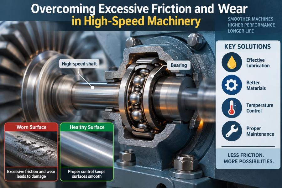

A production line is running normally until a bearing housing becomes too hot to touch. A pump begins to sound rough, a gearbox draws more power than usual, or a spindle loses the accuracy it had only weeks ago. These problems often look sudden from the outside, but the damaging process may have been developing quietly for a long time.
High-speed machinery makes friction and wear especially demanding. At high rotational speed, a small lubrication error, slight imbalance, or modest temperature rise can quickly become vibration, surface damage, lost efficiency, and unplanned downtime.
The challenge is not to eliminate friction completely; that is neither possible nor always desirable. The engineering task is to control where friction occurs, how much heat it produces, and whether contacting surfaces remain protected under real operating conditions.
Understanding the mechanisms behind excessive friction and wear helps operators recognize early warning signs, helps designers make better choices, and helps maintenance teams correct root causes rather than repeatedly replacing damaged parts.
⚙️ Why High Speed Changes the Problem
Speed magnifies nearly every tribological problem. Tribology is the engineering study of friction, lubrication, and wear between interacting surfaces. A shaft turning faster passes through more contact cycles each second, while churning losses, centrifugal forces, and heat generation can rise sharply.
A component that performs acceptably at low speed may fail at high speed because its lubricant cannot reach the contact reliably, its cage becomes unstable, or its balance error creates excessive radial force. Speed must therefore be treated as a system condition, not merely a line on a motor nameplate.
🧲 Friction Is Not a Single Phenomenon
Friction can occur between solid surfaces, within a lubricant, and as a component moves through air or fluid. In a rolling-element bearing, for example, friction comes from rolling contact, sliding at raceway contacts, seal drag, cage motion, and lubricant shearing.
Some friction is useful: a belt drive needs grip, and a clutch needs controlled friction to transmit torque. Trouble begins when friction is uncontrolled, concentrated in a small area, or converted into heat faster than the machine can reject it.
🔥 The Heat-Generation Feedback Loop
Frictional power becomes heat. As temperature rises, lubricant viscosity often falls, clearances change through thermal expansion, and protective films may become thinner. Those effects can increase friction further, creating a harmful feedback loop.
Consider a hypothetical high-speed electric motor bearing with slightly low grease fill. If the contact becomes poorly lubricated, temperature climbs. The grease may then oxidize or bleed oil less effectively, leaving the contact even less protected and accelerating the damage.
🛢️ Lubrication Regimes Explain Surface Protection
The condition of the lubricant film determines whether surfaces are separated or repeatedly touch. The most useful categories are boundary, mixed, and full-film lubrication.
| Regime | Surface condition | Typical concern in fast machinery |
|---|---|---|
| Boundary | Protective chemical films carry much of the load | High risk of adhesive wear and scuffing |
| Mixed | Lubricant film carries some load; asperities still touch | Common during starts, transients, or poor supply |
| Full-film | Lubricant largely separates surfaces | Viscous drag and temperature may become limiting |
Asperities are the microscopic high points on surfaces that appear smooth to the eye. Even well-machined parts have them, and their repeated contact can initiate wear when film thickness is inadequate.
🧪 Viscosity Must Match Speed, Load, and Temperature
Viscosity is a fluid’s resistance to flow. A lubricant that is too thin may not form an adequate separating film under load. One that is too thick may create excessive churning, drag, and heat at high speed.
The correct grade depends on bearing type, load, operating speed, lubricant delivery method, and actual stabilized temperature. Selecting oil only by ambient conditions is a common mistake, because the lubricant experiences the temperature inside the contact and housing, not the room temperature.
💧 Too Much Lubricant Can Be Harmful
More grease is not automatically safer. In a rapidly rotating bearing, excess grease can be churned by rolling elements and cages, increasing temperature and causing the grease structure to break down. The result can be leakage, oil separation, and ultimately poor lubrication where it is needed.
Oil systems can suffer similarly if sump levels are too high. Rotating gears or shafts may whip the oil into foam, entrain air, and consume power. Manufacturers’ fill guidance and observed operating temperature should govern practice, not the instinct to overfill.
🌬️ Air, Foam, and Cavitation Disrupt the Oil Film
Entrained air lowers the effective stiffness of the lubricant and can reduce film reliability. Foam also interferes with heat transfer and may cause erratic delivery through lines, nozzles, and restrictors.
In pumps and hydraulic systems, local pressure can fall enough for vapor cavities to form and collapse. This is cavitation. It can erode surfaces, create noise and vibration, and contaminate the fluid with wear particles. Proper suction conditions and air-tight connections are as important as fluid selection.
🧹 Contamination Turns Lubricant into an Abrasive
Hard particles in oil or grease can pass through narrow contacts and cut, indent, or fatigue surfaces. Contamination may enter through damaged seals, poorly cleaned fill ports, dirty tools, breather systems, or wear generated inside the machine itself.
Particle size matters relative to contact film thickness. A particle that seems insignificant in a sample bottle may be large enough to disrupt a micrometre-scale lubricant film. Clean handling, suitable filtration, and sealed storage are practical wear-control measures.
🔍 Wear Debris Is Both Symptom and Cause
Once wear starts, the debris it produces can accelerate further wear. Metallic particles may circulate through bearings, gears, valves, and seals, creating a self-sustaining damage cycle.
Oil analysis can help distinguish broad patterns, such as rising ferrous debris, water contamination, viscosity change, or depleted additives. It is a trend tool rather than a stand-alone diagnosis; sample location, interval, machine history, and operating duty all affect interpretation.
⚖️ Misalignment Concentrates the Load
Misalignment forces shafts, couplings, belts, bearings, and seals to operate at angles or offsets they were not designed to tolerate. It concentrates load on part of a bearing raceway or gear tooth, reducing the useful contact area and increasing local stress.
High speed makes the consequences more severe because the overloaded region experiences many stress cycles in a short time. Precision alignment should account for thermal growth, pipe strain, base movement, and the machine’s expected operating position rather than relying only on a cold measurement.
🎯 Imbalance Creates Repeating Dynamic Forces
An unbalanced rotor has its mass center offset from its axis of rotation. As speed rises, the resulting centrifugal force rises strongly, transmitting repeating loads into bearings and supports.
Balance correction is not simply adding or removing mass until vibration falls at one condition. The rotor’s service speed range, flexibility, assembly method, and location of correction planes all matter. A rotor that is acceptable at one speed can encounter a critical response at another.
📈 Resonance Amplifies Small Excitations
Every structure has natural frequencies. When operating speed or a forcing frequency approaches one of them, vibration can be amplified dramatically; this condition is resonance.
Excessive vibration causes micro-sliding, fretting, looseness, and fatigue in components that may otherwise have adequate strength. Avoiding problematic speed ranges, increasing support stiffness, changing mass distribution, or improving damping are possible responses, but the correct choice depends on the machine’s dynamic behavior.
🪛 Bearing Fits and Internal Clearance Matter
Bearings require carefully selected shaft and housing fits. A loose inner ring can creep on a shaft, while an excessively tight fit can reduce internal clearance and preload the bearing beyond its intended condition.
At high speed, thermal differences between shaft, inner ring, outer ring, and housing change these relationships. Installation force should be applied to the ring being fitted, not transmitted through rolling elements. Striking a bearing directly is a reliable way to create early damage.
🏗️ Preload Is Useful but Sensitive
Angular-contact ball bearings and some precision spindle arrangements use preload to improve stiffness and position control. Proper preload limits unwanted motion, but too much raises contact stress, heat, and fatigue risk.
Preload is therefore a design and assembly variable, not a generic maintenance adjustment. Spacer geometry, temperature distribution, speed, and bearing arrangement all influence the final condition. A machine may need a deliberately chosen preload strategy that differs from a slower, heavier-loaded machine.
🦷 Gear Contacts Need More Than Strong Teeth
High-speed gears must transmit load through a thin elastohydrodynamic lubricant film, where pressure increases viscosity locally and helps support the load. Tooth geometry, surface finish, alignment, lubricant properties, and oil temperature all affect that film.
Scuffing often occurs when sliding and temperature overwhelm the protective film, while pitting and micropitting are fatigue-related surface failures influenced by stress cycles and film quality. Changing oil may help, but it cannot compensate for poor tooth contact caused by alignment or housing distortion.
🧊 Thermal Expansion Changes Clearances
Parts do not heat uniformly. A shaft near a hot rotor can expand faster than its housing, while an oil jet can cool one region more than another. These gradients can change bearing clearance, seal contact force, gear mesh, and alignment during operation.
Designers use material selection, cooling paths, controlled fits, and thermal models to manage these changes. Maintenance teams should recognize that measurements taken immediately after shutdown may not represent the machine’s stabilized running geometry.
🧱 Surface Finish Has a Functional Role
A mirror-like finish is not always optimal, and a rough finish is not always unacceptable. The target texture depends on the lubrication regime and component function. A surface needs enough quality to avoid severe asperity interaction, while some contacts benefit from texture that helps retain lubricant.
Grinding burns, directional machining marks, embedded abrasive, and poorly controlled finishing can create local defects that become wear initiation sites. Surface inspection should consider form, waviness, roughness, and evidence of thermal or handling damage.
🧬 Materials and Coatings Must Work as a Pair
Material choice affects hardness, toughness, corrosion resistance, thermal expansion, and compatibility with the lubricant and mating surface. A harder component may resist abrasion, but excessive hardness without adequate toughness can introduce another failure mode.
Coatings such as diamond-like carbon, thermal spray layers, or specialized anti-wear treatments can reduce friction or improve resistance under certain conditions. They are not universal fixes. Coating adhesion, surface preparation, counterpart material, load, temperature, and lubricant additives must be considered together.
🔩 Seals Protect, but They Add Drag
Seals keep contaminants out and lubricant in, yet contact seals create friction and heat. At high surface speed, seal lip material, shaft finish, lubrication, runout, and pressure difference become critical.
A seal that is too aggressive can overheat and wear its track. A seal with insufficient contact may leak or admit contaminants. Non-contact labyrinth and clearance seals reduce drag but may offer less protection in dirty or wet environments. The suitable design depends on the exposure.
🚦 Starts, Stops, and Speed Transients Are Critical
Steady running is only part of a machine’s duty cycle. During startup, lubricant films may not yet be established. During rapid acceleration or deceleration, loads and temperatures can shift faster than the lubrication system responds.
Frequent start-stop operation can therefore cause more wear than continuous operation at the same peak speed. Pre-lubrication, controlled ramp rates, warm-up routines, and appropriate standby oil circulation can reduce this vulnerability where the equipment design supports them.
📊 Monitor Trends Rather Than Waiting for Failure
Condition monitoring provides early evidence that friction or wear is changing. Useful signals include bearing and oil temperature, vibration, acoustic emissions in specialized applications, motor current, oil cleanliness, lubricant condition, and leakage.
No single measurement tells the full story. A temperature increase could result from a higher process load, altered ambient conditions, lubrication trouble, or sensor error. Reliable diagnosis compares multiple trends with operating speed, load, and maintenance history.
📳 Vibration Patterns Can Narrow the Search
Vibration analysis often helps identify whether a problem is associated with rotational speed, gear mesh, bearing defect frequencies, looseness, or resonance. It is particularly valuable when a machine cannot be dismantled without major disruption.
Interpretation requires care. A frequency peak is evidence, not a final verdict. Structural transmission paths, variable speed operation, sensor mounting, and nearby equipment can complicate the signal. Use vibration findings alongside inspection and lubrication evidence.
🛠️ Installation Quality Sets the Starting Point
Many premature failures begin before the machine is commissioned. Incorrect shaft preparation, poor cleanliness, improper heating of interference-fit parts, damaged threads, soft foot, pipe strain, and inaccurate alignment can all create conditions that high speed later exposes.
- Verify shaft and housing dimensions, roundness, and surface condition.
- Use calibrated tools and documented tightening procedures.
- Control cleanliness during assembly, especially around bearings and oil lines.
- Confirm free rotation and expected endplay or preload before operation.
- Record baseline vibration and temperature after commissioning.
🧾 Root-Cause Analysis Prevents Repeat Failures
Replacing a failed bearing without explaining why it failed often restarts the same cycle. A useful investigation examines physical evidence: raceway marks, cage condition, lubricant appearance, wear debris, fit marks, seal condition, alignment records, and operating trends.
For example, a discolored bearing may indicate overheating, but overheating is a symptom. The underlying cause could be excess grease, incorrect clearance, inadequate oil flow, electrical current damage, or a load problem. The repair should address the cause, not only the discoloration.
⚡ Electrical Currents Can Damage Bearings
Variable-frequency drives and other electrical systems can create shaft voltages in some motor arrangements. If current discharges through a bearing, it can produce fluting: a patterned damage feature on raceways that is often accompanied by elevated noise and vibration.
Grounding arrangements, insulated bearings, shaft grounding devices, and appropriate drive-system design may be used to manage this risk. Selection should be based on the electrical configuration and manufacturer guidance, not on visual symptoms alone.
🧭 A Practical Troubleshooting Sequence
When friction, temperature, or wear rises unexpectedly, avoid immediately changing several variables. That can destroy diagnostic evidence and make later comparison difficult.
- Confirm the measurement and compare it with speed, load, and ambient conditions.
- Check lubrication level, delivery, viscosity condition, contamination, and leaks.
- Review recent changes in process duty, assembly work, settings, or lubricant type.
- Inspect for alignment, balance, looseness, abnormal noise, and thermal distortion.
- Plan targeted testing or controlled shutdown inspection if the risk warrants it.
Safety comes first. Hot surfaces, rotating equipment, pressurized lubrication lines, and stored energy require site-specific isolation and inspection procedures.
🧠 Design for the Actual Duty Cycle
Robust high-speed machinery is designed around real duty, not idealized maximum rpm alone. The design must account for load spectrum, starts and stops, ambient temperature, contamination exposure, maintenance capability, and consequences of a shutdown.
A lubrication system that works in a clean test environment may be unsuitable near water, dust, process chemicals, or frequent thermal cycling. Likewise, an extremely precise system can be difficult to sustain if field maintenance cannot verify its critical settings.
🌟 The Core Principle: Control the Entire Tribology System
Excessive friction and wear rarely come from one isolated choice. They emerge from the interaction of surfaces, load, speed, lubricant, contamination, heat, alignment, dynamics, assembly, and operating practice.
The most durable solution is usually systematic: maintain a stable lubricant film, keep contaminants out, control forces and temperatures, preserve correct geometry, and use condition trends to intervene before surface damage becomes severe. That approach improves reliability without assuming that one oil, coating, or monitoring device can solve every problem.
High-speed machinery lasts longer when friction is managed as a whole-system engineering problem rather than treated as a single-component failure. Careful design, disciplined installation, clean lubrication, and evidence-based maintenance turn that principle into dependable operation. ⚙️🛢️📈