
A maintenance team needs a replacement bracket before the next production shift. A product designer needs to test whether a new enclosure can be assembled comfortably. A tooling engineer needs a fixture that holds an awkward casting securely for machining. These problems look different, but they share a familiar constraint: conventional manufacturing may take longer to organize than the part takes to make.
Additive manufacturing offers another route. Instead of removing material from a block or forming it in a dedicated tool, it builds a component layer by layer from digital geometry. That changes the speed of iteration, the economics of low-volume work, and even the shapes engineers can reasonably consider.
Yet a printed part is not automatically a production-ready part. Material behavior, surface quality, orientation, inspection, post-processing, and safety requirements still govern whether it performs its intended job.
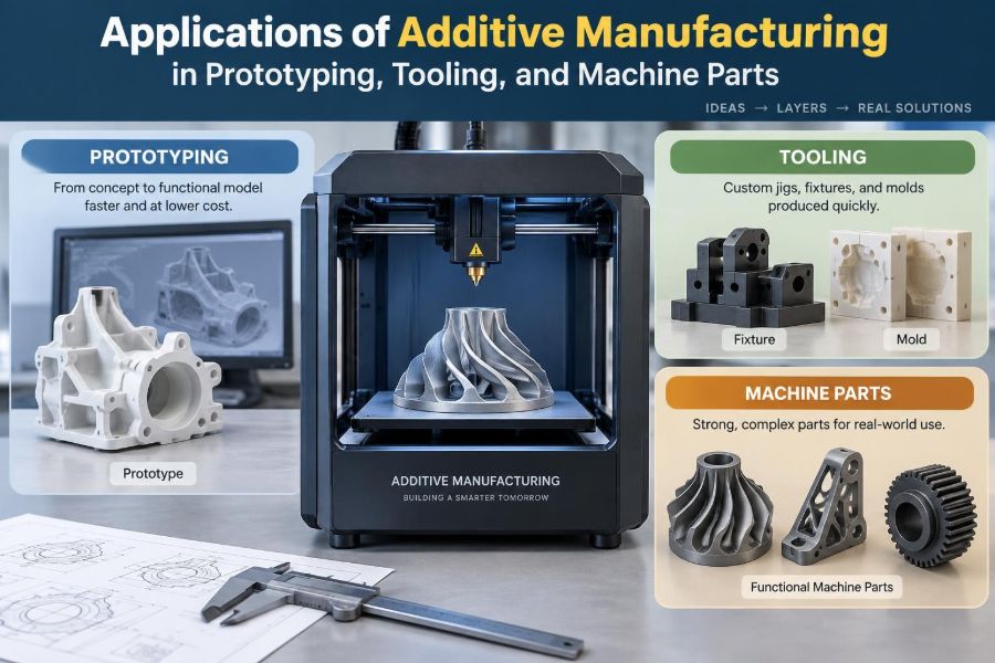
The useful question is therefore not “Can this be printed?” but “Where does additive manufacturing create the most engineering value?” The answer is clearest in prototypes, tooling, and carefully selected machine parts.
🧱 Additive Manufacturing in Practical Terms
Additive manufacturing, often called 3D printing, creates an object by depositing, curing, sintering, or fusing material in successive layers. The process begins with a digital 3D model, which is divided into thin cross-sections by software called a slicer.
Different systems use polymers, photopolymer resins, metal powders, ceramic-filled materials, or wire feedstock. Their outputs may look alike at first glance, but their strength, accuracy, temperature resistance, and finishing needs can differ substantially.
🗂️ Three Applications, Three Different Goals
Prototyping seeks rapid learning. Tooling seeks repeatability, operator usability, and a controlled manufacturing process. Machine-part production seeks reliable function under defined loads and environments.
Confusing these goals creates costly decisions. A low-cost polymer prototype may be excellent for checking fit but unsuitable for a heated production fixture. A metal part may survive a load test but still be unacceptable if its fatigue life, porosity, or internal geometry has not been verified.
⚖️ Why the Business Case Changes at Low Volume
Conventional processes often require dedicated setup: molds, dies, fixtures, programming, purchased stock, and machine time. Once that preparation is complete, making many identical pieces can be efficient.
Additive manufacturing shifts more effort toward the digital stage and less toward dedicated physical tooling. This is especially useful for one-off items, small batches, frequent design changes, and geometries that would require multiple machining setups or assembly operations.
For high-volume simple parts, molding, stamping, casting, or machining may still be the stronger choice. The best process depends on total cost, not on printing time alone.
🧭 Choosing the Right Additive Process
Process selection should begin with the required function rather than the available printer. Fused-filament extrusion is accessible and useful for many concept models and shop aids. Vat photopolymerization can provide fine detail and smooth surfaces, while powder-bed polymer processes can build multiple parts without extensive supports.
Metal powder-bed fusion, binder jetting, directed energy deposition, and wire-based systems serve different material and size ranges. Their capabilities are not interchangeable.
| Process family | Common strengths | Typical engineering use |
|---|---|---|
| Material extrusion | Low cost, quick iteration | Concept models, protective aids, light-duty fixtures |
| Vat photopolymerization | Fine detail, smooth surfaces | Visual models, patterns, fit checks |
| Polymer powder bed | Complex shapes, nested builds | Functional polymer housings and ducts |
| Metal powder bed | Complex metal geometry | High-value components, conformal cooling inserts |
| Directed energy systems | Repair and larger metal deposition | Feature addition, refurbishment, near-net shapes |
🧪 Materials Are Engineering Decisions
Calling a part “plastic” or “metal” is not enough. Polymer choices differ in stiffness, impact resistance, moisture uptake, chemical resistance, and temperature capability. Metal alloys differ in corrosion behavior, weldability, hardness response, creep resistance, and fatigue performance.
Material data sheets are a starting point, not a blanket guarantee. Printed properties can vary with machine settings, build direction, layer thickness, heat treatment, and part geometry. Engineers should use data relevant to the specific process and condition being considered.
📐 Design for Additive Manufacturing, Not Just Printability
Design for additive manufacturing, or DfAM, means using additive freedom deliberately while respecting process constraints. It includes wall thickness, escape paths for trapped powder or resin, support access, tolerances, and the orientation of critical surfaces.
A part that barely prints is not necessarily a good design. A better design is one that can be made consistently, cleaned, inspected, and used without fragile features or avoidable finishing work.
🔄 Prototypes Turn Assumptions into Evidence
Engineering drawings and CAD models communicate intent, but physical prototypes expose assumptions. A housing may appear compact on screen yet block access to a connector. A handle may look ergonomic but force an uncomfortable wrist angle. A duct may fit geometrically but create unexpected assembly interference.
Rapid additive prototypes allow teams to answer these questions before committing to expensive tooling or long-lead manufacturing. The gain is not merely speed; it is earlier, better-quality feedback.
👀 Appearance Models Clarify Product Decisions
Appearance prototypes are often used to review size, color, surface texture, user interaction, and visual proportion. They can help design, manufacturing, marketing, and service teams discuss the same physical object rather than interpret a rendered image differently.
These models should not be mistaken for functional proof. A carefully finished resin shell may look close to a final product while having very different impact resistance, ultraviolet stability, or fastening behavior.
🔩 Functional Prototypes Test Real Interfaces
Functional prototypes are selected and built to test a defined behavior: snap-fit force, flow passage, cable routing, vibration clearance, sealing arrangement, or temporary load capacity. Their value increases when the test objective is explicit.
For example, a printed pump-cover prototype might be used to verify bolt access and gasket placement, not to validate long-term pressure containment. Defining that boundary keeps a useful test from becoming an unsupported conclusion.
🧩 Fit, Form, and Function Are Separate Checks
Engineers often use the phrase “fit, form, and function,” but each demands different evidence. Fit concerns interfaces and tolerances. Form concerns geometry and human interaction. Function concerns loads, temperatures, movement, fluids, electricity, or other operating conditions.
A prototype can pass one category and fail another. Treating them separately helps teams choose an appropriate material, test method, and level of confidence.
🏃 Iteration Becomes a Normal Design Activity
When a revised prototype can be produced without new molds or extensive setup, iteration becomes less intimidating. Designers can test two rib layouts, several grip diameters, or alternate duct shapes in parallel.
This does not remove the need for change control. Each version should be identified, its purpose documented, and its test results connected to the corresponding CAD revision. Fast fabrication without disciplined records can create confusion just as quickly.
🧰 Tooling Is Often the Highest-Value Use
Many additive manufacturing successes are not customer-facing parts at all. They are jigs, fixtures, drill guides, gauges, masks, assembly nests, and handling aids used inside the factory.
These tools are typically low volume, specific to one task, and frequently revised as a process matures. Their value comes from reducing setup time, preventing incorrect orientation, improving consistency, or making an operation safer and less tiring.
🎯 Jigs and Fixtures Improve Repeatability
A jig guides a tool or operation; a fixture holds a workpiece in a known position. Additive manufacturing can create locating features, contoured supports, labels, and lightweight handles in one integrated body.
Consider a hypothetical fixture for drilling an irregular molded component. A printed nest can support its curved surfaces and guide the drill at the desired location. Wear surfaces or bushings may still need metal inserts, but the surrounding geometry can be made quickly.
📏 Gauges and Inspection Aids Reduce Ambiguity
Go/no-go gauges, profile templates, inspection nests, and visual boundary markers help operators make consistent decisions. A printed gauge is especially useful when it replaces improvised rulers, hand-marked templates, or repeated interpretation of a drawing.
For critical acceptance decisions, gauge accuracy and stability must be demonstrated. Temperature changes, polymer creep, moisture absorption, and wear can make an otherwise convenient gauge unsuitable for precise metrology.
🛠️ Assembly Aids Support People as Well as Parts
Assembly tools can prevent scratches, organize components, hold connectors during insertion, or present a part at a comfortable angle. These improvements are easy to overlook because they may not change the product geometry.
They can still reduce variation. A simple poka-yoke feature—an element that makes incorrect assembly difficult—may prevent a reversed component or wrong fastener from reaching the next station.
🌡️ Conformal Cooling Changes Tool Insert Design
Conformal cooling refers to internal channels that follow the contours of a mold or tool insert more closely than straight drilled passages can. Metal additive manufacturing can create these channel paths inside a solid component.
More uniform cooling can be valuable where conventional channels cannot reach critical regions. However, channel roughness, powder removal, pressure drop, corrosion, inspection access, and repairability must be addressed during design rather than after printing.
🧱 Hybrid Tooling Combines Processes Wisely
Tooling does not have to be entirely printed. A practical hybrid approach may use a printed body with hardened pins, threaded inserts, bushings, machined datum faces, or a standard clamping mechanism.
This approach assigns each process where it works best. Additive manufacturing supplies complex, customized geometry; conventional manufacturing supplies durable precision surfaces and standard components.
⚙️ Machine Parts Benefit When Geometry Matters
Additive manufacturing becomes compelling for machine parts when geometry provides a functional advantage: internal flow paths, reduced mass, consolidated assemblies, customized interfaces, or difficult-to-machine shapes.
A replacement part is not automatically a candidate simply because the original is unavailable. The engineer must still understand its duty cycle, load path, failure consequences, material requirements, and relevant dimensional interfaces.
🌬️ Internal Channels Enable New Flow Paths
Layered fabrication can form internal passages that are difficult or impossible to drill, mill, or assemble conventionally. Examples include compact manifolds, cooling passages, air distribution components, and sensor-routing cavities.
Internal complexity must serve a measurable purpose. Tight turns, rough surfaces, and inaccessible cavities can increase pressure loss or make cleaning difficult. A smooth-looking CAD channel does not guarantee a smooth as-built internal surface.
🪶 Lightweighting Requires Load-Path Thinking
Topology optimization and lattice structures can remove material from regions that contribute little to stiffness or strength under specified loads. The result may be a lighter part with a more organic form than conventional design normally permits.
But lightweighting is not decorative complexity. The loading assumptions, boundary conditions, buckling risk, vibration response, manufacturability, and inspection plan must all be credible. A lattice can be difficult to clean, coat, measure, or protect from damage.
🔗 Part Consolidation Can Remove Failure Points
A conventional assembly may contain brackets, fasteners, seals, spacers, and tubes because each element was easier to manufacture separately. Additive manufacturing can sometimes merge several of these functions into one part.
Fewer joints can reduce assembly time and eliminate leak paths or loosened fasteners. On the other hand, consolidation may make repair harder: if one feature wears out, the entire integrated component may need replacement.
🔧 Repair and Refurbishment Are Specialized Uses
Directed energy deposition and related metal deposition methods can add material to worn or damaged regions, followed by machining to restore critical dimensions. This is different from printing a complete replacement from scratch.
Repair work demands careful assessment of the original material, contamination, residual stress, heat input, bond quality, and geometry. For safety-critical equipment, repair approval and verification requirements may be more demanding than producing a new noncritical part.
📊 Orientation Influences Performance
Build orientation affects support requirements, surface finish, dimensional accuracy, printing time, and—especially in some processes—directional mechanical behavior. Layer interfaces can be weaker or behave differently than material within a layer.
Place critical holes, sealing faces, bearing seats, and highly loaded features with post-processing in mind. Orientation is therefore a design decision, not merely a software setting chosen at the last minute.
🧹 Post-Processing Is Part of Manufacturing
Printed components commonly need support removal, depowdering, curing, stress relief, heat treatment, machining, polishing, coating, or sealing. These steps may dominate lead time and cost for a precision part.
Designers should provide access for tools and media, specify where material can be removed, and avoid hidden regions that cannot be cleaned. A part is not manufacturable if the necessary post-processing cannot be performed safely and repeatably.
📐 Tolerances Need an Honest Strategy
Additive processes can achieve useful accuracy, but they do not eliminate variation. Shrinkage, thermal distortion, recoater interaction, support scars, and machine calibration can affect geometry.
Use additive manufacturing for the complex near-net shape, then machine critical datums, threads, bores, and sealing faces when appropriate. Tolerance requirements should be assigned according to functional need, not copied indiscriminately across every feature.
🔍 Inspection Must Match the Failure Risk
Inspection may include visual checks, dimensional measurement, mass comparison, pressure testing, density evaluation, computed tomography, or destructive test coupons. The right method depends on what could fail and how that failure would matter.
For a light-duty assembly aid, a functional trial may be sufficient. For a pressure-bearing or fatigue-loaded metal component, internal defects and material condition may require much more rigorous qualification. Printing a part is only one step in establishing confidence.
⚠️ Common Mistakes in Additive Adoption
The most common error is treating additive manufacturing as a direct substitute for every machined or molded part. That often produces expensive builds with unnecessary supports, poor surface quality, or unsuitable materials.
- Printing final-use parts with prototype-grade material assumptions.
- Ignoring cleaning and powder-removal routes in enclosed cavities.
- Specifying tight tolerances without a finishing plan.
- Using a printed tool beyond its temperature, load, or wear limit.
- Skipping documentation because the component was made quickly.
These are process-planning failures, not evidence that the technology lacks value.
🦺 Safety, Quality, and Digital Control Matter
Powders, resins, solvents, hot surfaces, moving equipment, and fine particulates can introduce hazards. Facilities need appropriate handling procedures, ventilation, personal protective equipment, housekeeping, and waste controls suited to their equipment and materials.
Digital control is equally important. Protect approved CAD files, maintain revision history, record build parameters where needed, and prevent obsolete files from becoming physical parts. The digital thread should connect design intent to the manufactured item.
💰 Calculate Total Cost Instead of Unit Price
A printed part with a higher direct material cost may still be economical if it avoids a long procurement delay, reduces assembly steps, eliminates a dedicated fixture, or prevents recurring process errors. Conversely, a fast print may become expensive after manual finishing and inspection.
Include design time, setup, machine utilization, post-processing, purchased inserts, testing, scrap risk, inventory, and downtime in the comparison. The relevant measure is the cost of meeting the required function reliably.
🧑🏭 A Practical Selection Workflow
A structured workflow keeps enthusiasm aligned with engineering evidence:
- Define the function, environment, loads, interfaces, and failure consequences.
- Identify whether the need is a prototype, tool, spare, or production component.
- Compare additive and conventional routes using total lead time and total cost.
- Select a process and material based on required properties and geometry.
- Design for build orientation, supports, cleaning, finishing, and inspection.
- Test the part at a level appropriate to its risk before broader use.
This sequence is simple, but it prevents many avoidable reprints and unsupported decisions.
🚀 Building Additive Capability Gradually
Organizations often gain more by starting with visible, low-risk applications than by immediately targeting the most demanding metal component. Shop-floor aids, fit-check models, ergonomic fixtures, and noncritical replacement covers build practical knowledge of design rules and workflow.
As capability grows, teams can develop approved materials, design guidelines, supplier qualification, inspection methods, and documented use cases. This creates a foundation for more consequential applications.
🎓 Skills Engineers Need Beyond CAD
Successful additive work blends mechanical design with manufacturing engineering, materials awareness, quality planning, and communication. Engineers need to ask where loads travel, how surfaces will be finished, how a cavity will be cleaned, and what evidence supports use.
They also need to explain limits clearly. Saying “this prototype validates assembly access but not pressure life” is a sign of sound engineering judgment, not a weakness.
🌍 The Core Principle: Use Complexity Purposefully
Additive manufacturing is most powerful when it reduces a real constraint: time to learn, tooling lead time, assembly complexity, inaccessible internal geometry, or the need to stock a rarely used component. It is less persuasive when used only because a part looks impressive when printed.
The strongest applications connect design freedom to a defined operational benefit and support that benefit with suitable material selection, post-processing, and verification. Complexity should earn its place by improving performance, manufacturability, or responsiveness.
Additive manufacturing delivers its greatest value when engineers treat it as a complete manufacturing system—not simply a machine that makes shapes. Used with that mindset, it can accelerate learning, strengthen production processes, and create machine components that conventional routes would struggle to produce. ⚙️🧰🔍