
A broken latch on a car glove box, a noisy fan bracket, or a cracked hinge on a folding chair can look like a small problem. Yet each part has traveled through a long chain of decisions before it reaches a customer: what it must do, what it can be made from, how it will be manufactured, and how failure will be prevented.
Mechanical parts are rarely designed in isolation. A simple-looking bracket may need to carry load, fit beside wiring, survive vibration, accept a fastener, resist corrosion, and be produced thousands of times without costly handwork. Changing one requirement often changes several others.
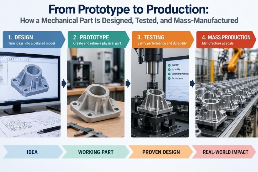
That is why the journey from a rough prototype to mass production is not a straight line from sketch to factory. It is a controlled cycle of learning, testing, correcting, and proving that a part works reliably under realistic conditions.
Understanding this process helps students connect theory to practice and helps working professionals make better decisions earlier, when changes are faster and less expensive. The following path applies to many mechanical products, from appliance mechanisms and industrial fixtures to automotive components and consumer hardware.
🧭 Start With the Function, Not the Shape
A sound design begins with a functional statement: what the part must accomplish in the larger assembly. “Support the motor at the required position while limiting vibration” is more useful than “make a metal bracket.” It directs attention to performance rather than appearance.
Engineers then identify interfaces: the surfaces, holes, clips, threads, or contacts through which the part connects to other components. A part can be strong by itself and still fail its purpose if its mounting pattern is wrong or its access for assembly is poor.
- What load, motion, force, or fluid does the part manage?
- Which components touch it, and in what sequence?
- What conditions define success or unacceptable failure?
📋 Convert Needs Into Engineering Requirements
Customer needs and design intent must become measurable requirements. These may include dimensions, allowable deflection, operating temperature, corrosion exposure, expected service life, appearance, mass, noise limits, and cost targets.
Requirements need priorities because they can conflict. Reducing mass may reduce stiffness; a polished cosmetic surface may increase finishing cost; and a very tight tolerance may demand a slower manufacturing process. A requirements document makes these tradeoffs visible instead of leaving them as assumptions.
Where uncertainty exists, engineers should record it. An estimated load is not the same as a verified load, and a provisional requirement should be marked as such until data improves.
🔍 Understand the Real Use Environment
Design loads are more than the obvious static force. A shelf bracket sees weight, but it may also see impacts when an object is dropped, cyclic bending from repeated use, humidity, accidental misuse, and vibration during transport.
The environment determines what must be investigated. A plastic clip near an engine experiences heat and chemicals; an outdoor enclosure sees ultraviolet exposure and moisture; a precision sliding mechanism may be affected by dust. Service conditions can be more demanding than a clean laboratory demonstration.
A useful practice is to map normal use, foreseeable misuse, storage, shipping, installation, and maintenance. The part must survive the full journey, not only its intended operating moment.
⚖️ Define Loads, Constraints, and Failure Modes
A load case describes how forces, moments, pressures, or temperatures act on the part. Constraints describe how the part is held or connected. Together, they determine stresses and deformation.
Engineers also ask how the part could fail. Common modes include yielding, fracture, buckling, wear, fatigue cracking, excessive deflection, leakage, loosening, creep, and resonance. A thin steel member may be strong in tension yet buckle under compression; a plastic part may slowly deform under a sustained load through creep.
Thinking in failure modes prevents a narrow focus on one stress value. The important question is not simply “Is the part strong?” but “Can this part fail in any credible way during its life?”
🧩 Generate Concepts Before Committing
Early concepts should explore different physical principles, not merely different styling. A cover can be retained with screws, snap fits, hinges, magnets, quarter-turn fasteners, or a sliding track. Each concept changes tooling, serviceability, load paths, and cost.
Sketches, simple models, and rough calculations are useful at this stage because they expose major problems quickly. A concept may be rejected because it requires an inaccessible screw, creates a sharp stress concentration, or needs a material incompatible with the operating temperature.
Teams often compare concepts against weighted criteria such as safety, performance, manufacturability, assembly time, cost, repairability, and environmental exposure. The highest-scoring option is not automatically selected, but the comparison makes the reasoning explicit.
📐 Build a Clear Load Path
A load path is the route force takes through a component and into the surrounding assembly. Good parts guide load through broad, direct sections. Poor parts force it through thin tabs, abrupt corners, unsupported fasteners, or isolated points.
Consider a wall-mounted hook. Its force should flow from the hook body into reinforced mounting regions and then into the wall fasteners. If the hook is attached to a thin decorative flange, the flange may bend long before the material reaches its nominal strength.
Ribs, gussets, flanges, and changes in section thickness can improve stiffness, but they must be placed where they redirect load effectively. Adding material everywhere usually raises cost and mass without solving the actual weakness.
🧱 Select Materials for the Whole Job
Material selection is a systems decision. Strength, stiffness, density, toughness, fatigue behavior, corrosion resistance, temperature capability, friction, electrical behavior, process compatibility, availability, and cost all matter.
Steel may offer high stiffness and familiar joining methods, while aluminum can reduce mass and resist many forms of corrosion. Engineering plastics can integrate clips and complex geometry, but may be sensitive to temperature, chemicals, moisture, or long-term loading. No material is “best” outside a specific application.
Material data sheets provide useful starting values, but actual performance depends on grade, processing route, thickness, fiber orientation in reinforced plastics, heat treatment, surface condition, and environment. Design allowables should reflect those realities.
🧪 Match the Material to the Manufacturing Process
The chosen material and process constrain one another. A part intended for injection molding needs suitable melt flow and cooling behavior. A deep-drawn sheet-metal part needs ductility. A machined component needs stock material that can be cut predictably and economically.
Process choices also change properties. Welding can introduce residual stress and a heat-affected zone. Casting can create porosity if process control is poor. Cold forming may strengthen some regions while reducing ductility. These are engineering inputs, not merely factory details.
Early conversations with material suppliers and manufacturing engineers can reveal whether a desirable specification is practical at production scale.
🖥️ Turn Intent Into a Parametric CAD Model
Computer-aided design, or CAD, turns a concept into controlled geometry. A parametric model uses dimensions and relationships so that a change to one value can update related features. This is especially helpful when mounting patterns, wall thicknesses, or envelope dimensions evolve.
A robust model reflects design intent. For example, holes may be located from functional datums rather than from arbitrary edges. A datum is a reference feature used to define location or orientation consistently.
CAD models should also include realistic neighboring parts. Interference checks can reveal collisions, inadequate tool access, pinched wiring, or insufficient clearance before physical parts are made.
📏 Use Tolerances to Control What Actually Matters
No manufactured dimension is exact. Tolerances define the acceptable variation in size, form, orientation, and location. They are necessary because a perfect drawing is impossible to produce repeatedly and impossible to inspect economically.
Tight tolerances belong on features that control function: a bearing seat, a sealing face, or the position of a locating hole. Applying them indiscriminately can increase machining time, scrap, inspection effort, and supplier difficulty.
Geometric dimensioning and tolerancing can describe relationships more clearly than separate plus-or-minus dimensions. For instance, it can control how perpendicular a mounting face must be to a reference plane, which may matter more than its individual linear dimensions.
🔗 Account for Tolerance Stack-Up
When several parts assemble together, their variations accumulate. This is called tolerance stack-up. A cover may be correctly made, and its mating housing may also be correctly made, yet the latch can misalign if several locating dimensions all drift in the same direction.
Engineers analyze critical stacks using worst-case assumptions or statistical methods when the production process and risk justify them. The right method depends on the consequence of failure and the amount of process knowledge available.
Datum strategy is central. Parts should locate from surfaces that are stable, accessible, and functionally relevant. Measuring one feature from a cosmetic edge while assembling from a different edge is a common source of confusion.
🧮 Use Analysis as a Decision Tool
Hand calculations provide rapid engineering judgment. They can estimate beam bending, bolt preload, pressure forces, heat transfer, shaft deflection, or natural frequency. Their value is not only the answer; they reveal which variables drive the design.
Finite element analysis, or FEA, divides a model into many small elements to estimate stress, strain, displacement, or temperature fields. It is powerful when geometry or loading is complex, but its output is only as credible as its assumptions.
Boundary conditions deserve special scrutiny. A simulation that restrains a part more rigidly than the real assembly can produce reassuring but misleading results. FEA should be checked against simple calculations, physical behavior, and later test data.
🌡️ Consider Heat, Motion, and Time
Many failures develop slowly. Thermal expansion can close clearances or overload fasteners. Repeated motion can wear a pivot. A spring can lose force over time, and a polymer latch can relax under sustained strain.
Moving assemblies need attention to friction, lubrication, surface finish, alignment, contact pressure, and contamination. A mechanism that works smoothly on a bench may bind after dust enters it or after thermal growth shifts two mating parts.
Time-dependent behavior is especially important for fatigue and creep. Fatigue damage comes from repeated stress cycles, sometimes at stress levels below the material’s one-time strength. Creep is progressive deformation under sustained load, often more pronounced at elevated temperature.
🛠️ Design for Manufacturability
Design for manufacturability, often shortened to DFM, means shaping a part so the intended process can make it consistently. It is not a final cost-cutting review; it should influence the first viable geometry.
An injection-molded part generally needs draft angle so it can leave the mold, reasonably uniform wall thickness to cool evenly, and ribs sized to avoid surface sink marks. A sheet-metal part needs bend radii, relief where bends meet edges, and features that suit available tooling.
Machining can make highly precise parts, but deep narrow pockets, tiny internal corners, and multiple awkward setups increase time and variation. DFM asks whether each feature earns its complexity.
🏭 Choose a Process That Fits Volume and Risk
The same geometry may be produced by machining, casting, forging, stamping, molding, additive manufacturing, or fabrication. The appropriate route depends on annual volume, required properties, geometry, finish, tolerance, tooling investment, and supply-chain capability.
| Process | Often suited to | Key tradeoff |
|---|---|---|
| Machining | Low volumes, prototypes, precision features | Flexible but can be slow and material-intensive |
| Injection molding | High-volume plastic parts | Fast repeatability but requires dedicated tooling |
| Stamping | High-volume sheet-metal parts | Efficient after tooling investment; geometry has forming limits |
| Casting | Complex metal shapes | Can reduce machining, but quality control is process-dependent |
Production process selection should happen before a design is frozen. A prototype made by machining may hide molding constraints, while a 3D-printed model may not represent the strength or surface quality of the intended production part.
🧰 Prototype With a Purpose
A prototype is an experiment, not simply a miniature version of the final product. The question being answered determines how closely it must resemble production hardware.
A rough 3D-printed housing may be ideal for checking hand clearance and assembly sequence. A machined metal prototype may be needed for structural testing. A pilot mold may be necessary to investigate shrinkage, cosmetic quality, and snap-fit behavior.
Label prototype limitations clearly. If a part is printed from a different polymer or built in a different orientation, test results may not transfer directly to an injection-molded production part.
🔬 Plan Verification Before Testing Begins
Verification asks whether the design meets its stated requirements. A verification plan links every important requirement to a method: inspection, analysis, demonstration, or physical test. This avoids discovering late that no one defined how a claim would be proved.
A good test plan specifies the sample condition, fixtures, loading method, measurement tools, acceptance criteria, and what constitutes a valid test. It also records deviations. A loose fixture or an uncalibrated sensor can make a technically impressive test difficult to trust.
Testing should reproduce the relevant physics, not necessarily every detail of field use. The fixture must not introduce an unrealistic load path that causes a failure unrelated to the product.
💥 Test Strength, Fatigue, and Abuse Resistance
Static testing applies a load once or slowly to examine strength, stiffness, or permanent deformation. It can reveal yielding, fracture, excessive deflection, or a weak attachment point. But many real products fail after repeated use rather than a single overload.
Fatigue testing cycles the part through representative loading. Test levels and cycle counts must be selected carefully: overly severe conditions can create an irrelevant failure, while mild conditions may not expose a weakness. Where accelerated tests are used, engineers need a defensible link to the expected damage mechanism.
Abuse testing explores foreseeable events such as drops, overtravel, misuse, or rough handling. It should distinguish between a cosmetic mark and a safety-critical loss of function.
🌦️ Test Environmental Durability
Temperature, humidity, moisture, ultraviolet light, salt exposure, chemicals, dust, and vibration can each change material behavior. Environmental testing helps identify whether a design remains functional after exposure, not merely whether it looks acceptable immediately afterward.
For example, a coated steel fastener system may need corrosion evaluation because corrosion products can seize threads or reduce clamping force. A plastic enclosure may need high- and low-temperature conditioning because dimensions and impact resistance can change with temperature.
Combined conditions can matter most. Vibration after thermal cycling, or mechanical loading after chemical exposure, may reveal an interaction absent from separate tests.
📊 Measure, Inspect, and Learn From Variation
Measurement is the bridge between design intent and physical reality. Inspection may involve calipers, gauges, coordinate measuring machines, optical systems, force sensors, or functional fixtures, depending on the feature and required uncertainty.
A measurement system must be capable of resolving the tolerance being controlled. If gauge variation is large relative to the permitted range, it becomes difficult to know whether a part is truly good or bad.
Inspection data should guide action. A consistent shift in hole position may indicate a fixture issue, tool wear, datum misunderstanding, or material movement. Sorting parts without finding the cause only delays the next problem.
🔁 Run a Pilot Build Before Full Release
A pilot build uses production-intent materials, tools, processes, and assembly methods as far as practical. It is where the design meets real cycle times, operator access, inspection routines, packaging, and supplier variation.
Problems at this stage are valuable discoveries. A screw may be difficult to start, a molded part may warp after ejection, or an operator may need two hands where the work instruction assumed one. These findings improve both product and process.
Engineering changes should be controlled through clear revision records. Production teams need to know exactly which drawing, material specification, tooling version, and inspection criteria apply to each build.
👷 Design for Assembly and Service
Design for assembly reduces unnecessary handling, orientation errors, and fastener count. Features such as asymmetric locating tabs, lead-in chamfers, captive hardware, and mistake-proofed connectors can make assembly faster and more reliable.
Serviceability deserves equal thought when a product will be repaired. A bearing that lasts well but requires dismantling an entire machine to replace may create avoidable lifecycle cost. Conversely, making every part easily removable can add cost and weaken sealing or stiffness.
The practical goal is appropriate access for the expected maintenance strategy, not maximum disassembly in every product.
🧯 Use Risk Reviews to Find Problems Early
Structured risk reviews encourage cross-functional teams to challenge assumptions. Failure mode and effects analysis, commonly called FMEA, is one method for listing potential failures, their effects, likely causes, existing controls, and actions to reduce risk.
The value is in the discussion, not a spreadsheet score alone. Manufacturing may identify a hard-to-control feature; quality may question inspectability; service teams may describe field handling; and designers may revise the geometry before expensive commitments are made.
Risk reviews should be revisited after test results, supplier feedback, and design changes. A new rib, coating, or assembly method can solve one problem while introducing another.
💰 Balance Unit Cost Against Total Cost
Unit price is only one part of cost. Tooling, fixtures, scrap, inspection, labor, shipping, warranty exposure, maintenance, and end-of-life handling can all influence the economic result.
For example, removing a locating feature might save a small amount of material but increase assembly time and misalignment risk. A more expensive corrosion-resistant material may reduce the need for coating steps and simplify the supply chain. The best choice depends on the entire system.
Cost reduction works best when it removes non-value-adding complexity without weakening the functional requirements that protect safety, reliability, or customer experience.
♻️ Consider Lifecycle and End-of-Life Choices
Mechanical design increasingly considers material use, repair, reuse, and recycling. These issues may influence how parts are joined, whether dissimilar materials can be separated, and whether a wear component can be replaced rather than forcing disposal of an entire assembly.
There are tradeoffs. A permanently bonded joint can improve sealing and structural performance but complicate disassembly. A multi-material design can provide excellent function but make material recovery more difficult. Engineers should evaluate the actual lifecycle priorities of the application.
Reducing mass, waste, and energy use is valuable when it does not simply transfer the burden to higher scrap rates, shorter life, or harder maintenance.
🚧 Avoid Common Prototype-to-Production Mistakes
Several recurring mistakes create costly late changes:
- Freezing geometry before the manufacturing process is chosen.
- Using prototype material behavior as proof of production performance.
- Adding tight tolerances without identifying the functional reason.
- Testing only the part, not the assembly and its real interfaces.
- Ignoring access for tools, operators, inspection, or service.
- Treating a passed test as permanent proof despite a later material, supplier, or geometry change.
The remedy is not more paperwork for its own sake. It is disciplined traceability between requirements, design decisions, process assumptions, and verification evidence.
🗂️ Control Changes Without Losing Design Intent
Production designs continue to evolve. A supplier may change a tool, a material becomes unavailable, or field feedback reveals an unexpected issue. Change control ensures that modifications are reviewed for their impact on fit, function, safety, reliability, process capability, and documentation.
Even apparently minor changes can matter. Moving a gate on a molded part may alter warpage; changing a fastener coating can alter torque-tension behavior; substituting a polymer grade can affect impact resistance or shrinkage.
Clear revision identification, updated drawings, and targeted re-verification protect the design intent as the product moves through its lifecycle.
🏁 The Core Principle: Design the System, Then Prove It
A reliable production part emerges from linked decisions, not from a single clever CAD model. Function defines requirements; requirements guide geometry and material; manufacturing constraints shape the design; prototypes answer focused questions; and tests provide evidence that the finished assembly performs as intended.
The strongest teams bring manufacturing, quality, supply, assembly, and service perspectives into the design process early. This does not eliminate iteration. It makes iteration purposeful, less expensive, and more likely to produce a part that can be built repeatedly.
Above all, treat each physical part as evidence. When a prototype bends, a tool marks a surface, or an inspection trend appears, the product is revealing something about the system. Listening to that evidence is how engineering moves from possibility to dependable production.
A mechanical part is truly ready for mass manufacture only when its function, material, geometry, process, inspection, and real-world behavior have been developed as one connected system. That mindset turns prototypes into reliable products rather than expensive surprises. ⚙️🔧🏭