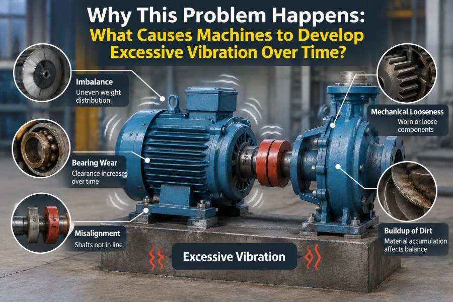

A pump that once ran with a steady hum begins to shake its pipework. A fan develops a low rumble that can be felt through the floor. A motor that passed acceptance testing now trips intermittently, even though no one has changed its speed or load.
These are familiar maintenance problems, but vibration is rarely just an annoyance. It can loosen fasteners, damage bearings, fatigue welded supports, degrade product quality, and make a small mechanical defect become an expensive shutdown.
Machines do not usually “start vibrating” for one simple reason. All rotating and reciprocating equipment generates some vibration by design. The real issue is that forces, clearances, stiffness, alignment, or operating conditions change over time until normal motion becomes excessive or destructive.
Understanding the cause means looking beyond the vibration reading itself. The pattern, direction, frequency, operating condition, and history of the machine all contain clues about what has changed.
🔄 Vibration Is Motion, Not Automatically a Fault
Vibration is repeated movement about a reference position. In a machine, that movement may be rotational, side-to-side, vertical, axial, torsional, or a mixture of several forms.
A rotating shaft with a slight mass imbalance, for example, creates a repeating radial force. A reciprocating compressor creates alternating forces as pistons change direction. These forces are expected; the engineering task is to keep them within acceptable limits.
Excessive vibration occurs when the force becomes too large, the structure becomes too responsive, or both. A machine can therefore become problematic without any dramatic visible damage.
📈 Why Vibration Often Grows Gradually
Many vibration faults form a feedback loop. Wear creates a little extra motion; that motion increases load, heat, or impact; the increased load accelerates wear. What begins as a barely detectable change may eventually become obvious to an operator.
Consider a bearing with declining lubrication quality. Friction and localized damage increase, clearance may grow, and the shaft can move more freely. The new motion can transmit greater force into the housing and connected machine components.
Trend data is valuable because a rising vibration level often reveals deterioration before the machine reaches a visibly damaged state.
⚖️ Mass Imbalance Creates a Repeating Centrifugal Force
Imbalance exists when a rotating part’s center of mass does not lie exactly on its axis of rotation. As the part spins, the offset mass produces a centrifugal force that pulls outward once per revolution.
Dirt buildup on a fan blade, erosion of a pump impeller, a missing balance weight, uneven blade repairs, or deposits inside a centrifuge can all change the mass distribution. Even a small mass error can create a significant force at high speed.
Imbalance commonly produces strong vibration at running speed, often called 1× rotational frequency. It is usually most evident in the radial direction, though the machine and support structure determine the exact response.
🌀 Deposits, Erosion, and Material Loss Change Rotors
Rotors do not remain geometrically perfect in service. Fans handling dusty air can accumulate uneven deposits. Pumps can suffer cavitation erosion. Process equipment can collect product residue on one side of a rotating element.
These conditions often cause an imbalance that changes with time or operating temperature. A fan may run smoothly after cleaning but become rough again as deposits return, which is a useful clue that cleaning alone has not addressed the process cause.
Material removal matters too. If one impeller blade erodes more rapidly than another, the rotor’s mass and aerodynamic or hydraulic loading become uneven.
📐 Misalignment Loads Parts That Should Run Freely
Misalignment occurs when coupled shafts are not positioned along the same intended centerline. The shafts may be offset in parallel, angled relative to one another, or both.
Flexible couplings can accommodate limited movement, but they do not make poor alignment harmless. Persistent misalignment imposes cyclic bending forces on shafts and couplings and raises bearing loads.
Common signs include elevated axial vibration, heat near coupling hubs, repeated coupling element failures, and bearing damage. These signs are not exclusive to misalignment, so measurements and inspection should confirm the diagnosis.
🌡️ Thermal Growth Can Undo a Good Alignment
A machine can be carefully aligned while cold and still operate misaligned once it reaches normal temperature. Motors, pumps, gearboxes, bases, and connected piping expand by different amounts and in different directions.
This is known as thermal growth. It is especially relevant where hot fluids, steam, heated gearboxes, or large temperature differences are present.
Alignment targets should therefore reflect the expected operating condition, not only the shutdown condition. A cold alignment value that looks imperfect may be intentional if it becomes correct at operating temperature.
🧱 Soft Foot Distorts the Machine Frame
Soft foot means one or more machine feet do not sit flat on the base when mounting bolts are loosened. Tightening the bolts then bends or twists the machine casing to force contact.
That distortion can alter shaft alignment, change bearing loading, and make alignment measurements inconsistent. It may also leave the machine sensitive to temperature changes and bolt tightening sequence.
Soft foot can result from warped feet, uneven grout, debris under shims, excessive or poorly stacked shims, or a distorted baseplate. Correcting it comes before final shaft alignment.
🔩 Mechanical Looseness Turns Small Forces into Impacts
Mechanical looseness is not one fault; it is a family of conditions involving unintended clearance or weak attachment. Loose bearing fits, worn housings, loose foundation bolts, cracked supports, and clearance in linkages all permit movement that should not occur.
Unlike smooth imbalance forces, looseness can produce impacts. The waveform may become irregular or contain harmonics—vibration components at multiples of running speed—because parts strike, shift, or briefly lose contact.
Do not assume every loose bolt is the root cause. A fastener may have loosened because vibration was already high, so inspection should ask why the joint lost preload.
🏗️ Weak Foundations and Flexible Structures Amplify Motion
The machine is only one part of the dynamic system. Its baseplate, foundation, steelwork, skid, piping, ducts, guards, and attached equipment all affect vibration.
A stiff, well-supported structure resists movement. A flexible support can deflect under normal dynamic forces, allowing the machine to move and changing the alignment or load path while it runs.
Grout deterioration, corroded structural members, cracked concrete, missing braces, and loosened anchor bolts can gradually reduce stiffness. The forcing mechanism may be unchanged, but measured vibration rises because the support has changed.
🎵 Resonance Makes Ordinary Forcing Forces Dangerous
Every structure has natural frequencies at which it prefers to vibrate. Resonance occurs when a forcing frequency, such as shaft speed, blade-pass frequency, or gear-mesh frequency, approaches a natural frequency.
At resonance, a modest force can create a large response, much as a playground swing moves farther when pushed at the right rhythm. A machine may be mechanically sound yet shake severely at one narrow speed range.
Changing speed, adding stiffness, changing mass, improving support, or modifying the excitation source may help. The correct remedy depends on a proper dynamic assessment; simply adding material to a structure can shift the problem rather than solve it.
⚙️ Bearing Wear Removes Precise Shaft Support
Bearings hold rotating shafts in a controlled position while allowing rotation. As rolling-element bearings wear or become damaged, internal clearance and surface roughness can increase, allowing abnormal shaft motion.
Defects on bearing races, rolling elements, or cages create characteristic repeating impacts. These often appear at frequencies related to bearing geometry rather than exactly at running speed.
Plain bearings have different failure mechanisms, including oil-film instability, clearance changes, wiping, and poor lubrication. Their vibration behavior should not be interpreted using rolling-element rules alone.
🛢️ Lubrication Problems Begin Before Bearings Fail
Lubricant separates moving surfaces, carries heat away, and protects against wear. Too little lubricant, unsuitable viscosity, contamination, water ingress, over-greasing, or degraded oil can all undermine that function.
Over-greasing is a frequent practical mistake. Excess grease can churn, create heat, and force lubricant where it should not go. More lubricant is not automatically better.
Oil analysis, grease condition, correct relubrication intervals, and clean handling practices provide useful evidence. However, lubrication findings should be considered alongside temperature, vibration, operating load, and inspection results.
💧 Contamination Accelerates Wear and Corrosion
Dirt particles, process chemicals, moisture, and metal debris can damage bearing surfaces, seals, gears, and hydraulic components. Abrasive particles create scratches and indentations that later become impact points.
Water can reduce lubricant effectiveness and encourage corrosion. Corroded bearing surfaces often become rough even if the machine was idle, which explains why equipment can show vibration problems shortly after a long standby period.
Good sealing and filtration are preventive measures, not cosmetic extras. They control the environment in which precision components must operate.
🦷 Gear Damage Adds Tooth-Mesh Excitation
Gear teeth transmit force through repeated contact. Their primary excitation occurs at gear-mesh frequency: the number of tooth engagements per unit time. Wear, chipped teeth, incorrect backlash, poor lubrication, or shaft misalignment can make that excitation stronger or more irregular.
A damaged tooth may create a repeating event once per gear revolution, often producing sidebands around gear-mesh frequency. This is why a spectrum is more informative than a single overall vibration number for gearbox diagnosis.
Gear noise and vibration can also rise when load changes. Before condemning gears, check oil condition, mounting rigidity, coupling alignment, and whether the driven process is imposing abnormal torque fluctuations.
🪜 Belt, Chain, and Coupling Drives Introduce Their Own Faults
Belts can be too loose, too tight, worn, contaminated, or mismatched. A loose belt may slip and whip; an over-tight belt can overload bearings. Pulley eccentricity and misaligned sheaves create additional periodic forces.
Chains may develop elongation, poor tension, worn sprockets, or inadequate lubrication. These defects can produce impact-like vibration and fluctuating torque.
Couplings also age. Elastomer elements harden or crack, metallic elements wear, and hub fits loosen. Replacing a failed coupling without correcting alignment, thermal growth, or driven-equipment loading often leads to repeat failures.
🌊 Hydraulic Problems Can Shake Pumps from Within
Pumps can vibrate because of mechanical defects, but the fluid system may be the real cause. Operating too far from the pump’s preferred flow range can create recirculation, unstable flow, pressure pulsation, and increased radial hydraulic forces.
Cavitation occurs when local pressure falls low enough for vapor bubbles to form and then collapse as pressure recovers. It can cause noise, vibration, surface damage, and reduced performance, although similar sounds can arise from air entrainment or turbulence.
Suction restrictions, blocked strainers, inadequate liquid level, hot liquid, poorly designed suction piping, and incorrect valve positions are among the conditions worth checking.
💨 Aerodynamic Instability Affects Fans and Compressors
Fans and compressors can experience unsteady flow when operating at unsuitable points on their performance curves. Flow separation, inlet distortion, rotating stall, or surge can generate pulsation and vibration.
A partially blocked inlet, a damper arrangement that creates swirl, dirty filters, or major duct changes can alter the inlet flow profile. The machine may be intact while its airflow environment is not.
Compressor surge is particularly significant because it involves large flow and pressure oscillations. It should be evaluated using the equipment’s operating data and control philosophy rather than diagnosed from vibration alone.
🔥 Process Changes Can Reveal a Hidden Mechanical Weakness
Vibration may rise after a production change even when no maintenance work was performed. Different fluid density, viscosity, temperature, pressure, throughput, or product composition can alter loads on pumps, mixers, fans, and conveyors.
For example, a mixer that handled a thin liquid may experience much higher torque fluctuations after a thicker batch is introduced. A marginally flexible support or worn bearing that was previously quiet may then become noticeable.
This does not mean the process change is wrong. It means the mechanical system must be checked against the new operating envelope.
⚡ Electrical Faults Can Produce Mechanical Vibration
Electric motors may transmit vibration caused by electromagnetic forces, unequal air gaps, rotor bar problems, eccentricity, or supply-related effects. These issues can create frequency components linked to line frequency and motor slip.
Electrical symptoms may overlap with mechanical ones. A motor that vibrates at a frequency related to the electrical supply may still also have imbalance or bearing wear.
Reliable diagnosis may require coordinated electrical testing, motor current analysis, vibration measurement, and inspection. Replacing bearings repeatedly will not correct an electromagnetic defect.
🔌 Variable-Speed Drives Change the Diagnostic Picture
Variable-speed drives allow useful control, but they also mean the machine passes through a range of forcing frequencies. A vibration peak that appears at one speed may indicate a structural resonance rather than a rotor fault.
Drive settings, acceleration rates, switching effects, and control behavior can influence the system, but they should not be blamed automatically. The mechanical train, process load, and support structure still require examination.
A controlled run-up or coast-down test can be helpful because it shows whether vibration peaks sharply at particular speeds. Safety procedures and equipment limitations must govern any such test.
📏 The Direction of Vibration Is a Useful Clue
Vibration measurements are commonly taken in horizontal, vertical, and axial directions at bearing locations. Comparing directions helps reveal how forces move through the machine.
High radial vibration can be consistent with imbalance, looseness, or structural flexibility. Strong axial vibration may support a misalignment hypothesis, especially near couplings. These are diagnostic clues, not standalone proof.
The phase relationship between sensors can add further information. Phase describes the timing of vibration relative to a reference; it is often useful for distinguishing imbalance, misalignment, and structural behavior.
📊 Overall Values Warn; Spectra Explain
An overall vibration value condenses broad vibration energy into one number. It is useful for trending and alarms, but it can hide the source of a change.
A frequency spectrum separates the signal into its component frequencies. It can show running speed, harmonics, bearing-related activity, gear mesh, blade-pass components, and electrical frequencies.
| Observation | What it may suggest | Why confirmation matters |
|---|---|---|
| Rise at running speed | Imbalance, eccentricity, or resonance | Several faults can excite the same frequency |
| Strong axial response | Misalignment or thrust-related loading | Pipe strain and structural paths can also contribute |
| Harmonics and impacts | Looseness, rubbing, or developing damage | Signal quality and operating condition affect interpretation |
| High-frequency bearing activity | Lubrication or rolling-element bearing distress | Mounting resonance can alter the measured response |
A spectrum is powerful when paired with machine speed, bearing data, process conditions, and prior measurements. It is not a fault label produced automatically by software.
🧭 Compare Like with Like When Trending
A useful trend compares measurements made under comparable conditions. Load, speed, temperature, product, valve position, and measurement location can all change vibration.
If a pump is measured at full flow one month and near shutoff the next, the difference may reflect hydraulic operation rather than deterioration. Record operating context with the reading.
Baseline data from a known-good condition is especially valuable. Without it, a single measurement can identify an abnormal condition but may not show whether the issue is stable, growing, or newly introduced.
🛠️ Installation Errors Often Become Long-Term Problems
Many chronic vibration issues begin at installation: inadequate base preparation, poor grouting, pipe strain, incorrectly tightened bolts, uncorrected soft foot, or alignment completed before connected piping is installed.
Pipe strain deserves attention. If piping pulls a pump nozzle out of position when bolts are tightened, the pump casing and shaft alignment can change. The machine may appear aligned when disconnected but not when connected to the real system.
Commissioning should verify the complete operating assembly, including guards, piping, ducts, electrical connections, and normal thermal conditions where practical.
🚫 Common Responses That Fail to Address the Cause
Some interventions reduce the visible symptom while leaving the mechanism active. Rebalancing a fan covered by recurring deposits, for example, may provide only temporary relief.
- Changing a bearing without investigating lubricant and fits: the replacement may fail in the same way.
- Tightening every bolt indiscriminately: this can distort housings or hide a cracked support.
- Adding rubber pads to every vibrating machine: isolation can help in the right application but may worsen alignment, stability, or resonance if poorly selected.
- Diagnosing from one reading: a single overall value cannot reliably separate the many possible causes.
Effective work connects the symptom to a physical mechanism, then checks whether the proposed repair removes that mechanism.
🧰 A Practical Investigation Sequence
A disciplined sequence prevents teams from jumping straight to the most familiar explanation. Start with safety: assess guards, hot surfaces, rotating parts, pressure, electrical hazards, and whether the machine can continue operating.
- Confirm the complaint and record speed, load, temperature, process condition, and recent changes.
- Inspect for loose hardware, leaks, rubbing, damaged guards, cracked supports, contamination, and abnormal heat.
- Measure vibration consistently in multiple directions and compare it with historical data.
- Review spectra, phase, waveforms, and process data where the tools and expertise are available.
- Check likely mechanical contributors such as soft foot, alignment, coupling condition, bearing fits, and foundation integrity.
- Verify hydraulic, aerodynamic, or electrical conditions before selecting a repair.
- Measure again after corrective work to confirm the response.
Complex systems may need a vibration specialist or the equipment manufacturer, particularly when resonance, instability, high-energy equipment, or safety-critical machinery is involved.
🛡️ Prevention Depends on Controlling Change
Long-term vibration control is less about one annual measurement and more about preserving the conditions that let equipment run correctly. That includes clean lubrication, sound seals, correct operating ranges, rigid support, proper alignment, and reliable installation practices.
Condition monitoring works best when it is connected to action. A trend should trigger inspection, planning, or a change in operating practice—not simply produce another report.
Operator observations also matter. A new sound, temperature, odor, or change in smoothness can provide the earliest indication that a trend is beginning.
✅ The Core Principle: Find the Force and the Response
Every excessive-vibration problem can be approached through two questions: what is creating the repeating force, and what is allowing or amplifying the resulting motion?
The force may come from imbalance, rubbing, gear contact, fluid pulsation, electromagnetic effects, or a changing process load. The response may be amplified by bearing clearance, weak support, looseness, misalignment, or resonance.
Thinking in this force-and-response framework prevents oversimplified diagnoses. It also explains why the same defect can be quiet in one installation and severe in another: the surrounding system changes the outcome.
Machines develop excessive vibration over time when wear, operating conditions, geometry, support stiffness, or energy input changes the balance between excitation and control. The best solution is therefore the one that removes the actual cause rather than merely reducing the measured symptom. ⚙️📈🔧