
A bicycle rider shifts to an easier gear before climbing a hill. A technician selects a reduction gearbox so a motor can turn a conveyor without stalling. Inside a cordless drill, several gears trade high motor speed for the twisting force needed to drive a screw.
These systems look different, but they depend on the same relationship: gears exchange speed for torque. The teeth make the motion predictable, allowing an engineer to calculate what happens at the output before building the machine.
That calculation is not just an academic exercise. A wrong ratio can leave a vehicle sluggish, overload a motor, make a robot miss its target speed, or cause a driven machine to run beyond its safe operating range.
Once the direction of each ratio is clear, gear-train problems become structured rather than mysterious. Start by identifying the driver and driven gears, then track speed, torque, direction, and real-world losses through the train.
⚙️ Start with the job the gear train must do
A gear train is a set of meshing gears used to transmit rotary motion and power between shafts. Its central purpose is usually to change rotational speed, torque, direction, shaft orientation, or some combination of these.
Before calculating anything, state the required output. Is the goal a slower shaft with more twisting force, a faster shaft with less force, a reversal of rotation, or a precise position relationship? The required function tells you whether a reduction, speed increase, or more specialized arrangement is appropriate.
🔄 Identify the driver and the driven gear
The driver is the gear receiving input power from a motor, engine, hand crank, or upstream shaft. The driven gear is the gear it directly turns.
In a simple pair, the driver’s teeth push against the driven gear’s teeth. Confusing these labels is the most common source of an inverted ratio. Mark the input shaft first, then follow the path of power one mesh at a time.
🦷 Why tooth count controls the motion
Meshing gears must pass the same number of teeth through their contact point in the same time. If a 20-tooth driver makes one revolution, 20 teeth move past the mesh. A 40-tooth driven gear therefore advances through only half of its full circumference.
For gears that mesh correctly, tooth count is the most convenient quantity for calculation. Pitch diameter can also be used, because tooth count and pitch diameter are proportional when gears share the same tooth size, or module/diametral pitch.
📐 Define gear ratio without reversing it
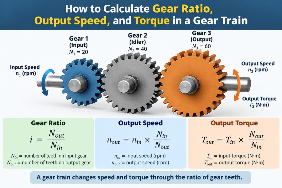
For output-speed calculations, define the gear ratio as:
Gear ratio, i = teeth on driven gear / teeth on driver gearWith this convention, a 20-tooth driver turning a 60-tooth driven gear gives i = 60 / 20 = 3, commonly called a 3:1 reduction. The input turns three times for every one output revolution.
Some books and industries write ratios in the opposite order, especially when describing speed ratio. That is acceptable only if the definition is stated and used consistently. Never rely on the phrase “3:1” alone without knowing which shaft is being compared.
🏎️ Calculate output speed from a simple gear pair
Rotational speed is often expressed in revolutions per minute, or rpm. For a simple external gear pair:
Output speed = input speed × (driver teeth / driven teeth)Equivalently, divide input speed by the gear ratio i. If a 20-tooth driver runs at 1,200 rpm and drives a 60-tooth gear, the output speed is 1,200 × 20 / 60 = 400 rpm.
A larger driven gear rotates more slowly because more teeth must pass through the mesh to complete one revolution.
💪 Calculate ideal output torque
Torque is the turning moment applied to a shaft. It is commonly expressed in newton-metres (N·m) in SI units or pound-force feet (lbf·ft) in US customary practice.
For an ideal gear pair with no losses:
Output torque = input torque × (driven teeth / driver teeth)Using the 3:1 example, an input torque of 10 N·m becomes an ideal output torque of 30 N·m. The slower output shaft can apply three times the torque, but it turns at one-third the speed.
⚖️ See the speed–torque trade-off
Gears do not create power. In an ideal system, reducing speed by a factor of three raises torque by a factor of three, so power remains unchanged.
Power = torque × angular speedAngular speed must be in radians per second when calculating power in watts. For quick comparisons at the same unit system, the key lesson is simpler: speed reduction multiplies torque, while speed increase reduces torque.
This is why a low bicycle gear helps on a hill. The wheel turns more slowly for each pedal revolution, but the rider can produce greater wheel torque.
↔️ Track the direction of rotation
Two ordinary external spur gears in direct mesh rotate in opposite directions. If the driver turns clockwise, the driven gear turns counterclockwise.
Each additional external mesh reverses direction again. Thus, a three-gear train with two meshes has the same output direction as the input. Direction matters in pumps, feed mechanisms, vehicle transmissions, and synchronized machinery, not only in classroom diagrams.
🧩 Understand what an idler gear changes
An idler gear sits between a driver and a driven gear. It transmits motion and may allow shafts to be spaced farther apart, but it does not change the magnitude of the overall speed ratio when its tooth count is considered only as an idler.
For example, a 20-tooth driver, 30-tooth idler, and 60-tooth output gear produce the same speed reduction as a direct 20-tooth-to-60-tooth pair: 3:1. The idler changes direction and geometry, not the ratio magnitude.
🧮 Multiply ratios in a compound gear train
A compound gear train has at least one shaft carrying two gears rigidly fixed together. Those gears have the same shaft speed, even if their tooth counts differ. This lets a designer obtain large reductions without a single enormous gear.
Calculate each mesh ratio, then multiply them:
Overall ratio = (driven 1 / driver 1) × (driven 2 / driver 2) × ...Keep the stages clearly labeled. The driven gear of one mesh may share a shaft with the driver of the next, but they are not necessarily the same physical gear.
🧱 Work through a two-stage reduction example
Suppose a 15-tooth motor pinion drives a 45-tooth gear on an intermediate shaft. A 20-tooth gear fixed to that shaft then drives an 80-tooth output gear.
- Stage 1 ratio:
45 / 15 = 3 - Stage 2 ratio:
80 / 20 = 4 - Overall reduction:
3 × 4 = 12:1
If the motor runs at 1,800 rpm, the ideal output speed is 1,800 / 12 = 150 rpm. With 5 N·m input torque, ideal output torque is 5 × 12 = 60 N·m before losses.
🔗 Use a power-flow table for complex trains
A compact table prevents the usual errors in multistage problems: mixing shaft speeds, applying a ratio backward, or losing track of which gear is fixed to which shaft.
| Stage | Driver teeth | Driven teeth | Stage ratio | Output speed relationship |
|---|---|---|---|---|
| 1 | 15 | 45 | 3:1 | Input ÷ 3 |
| 2 | 20 | 80 | 4:1 | Stage 1 output ÷ 4 |
| Overall | — | — | 12:1 | Input ÷ 12 |
Add a direction column when rotation sense matters. A sketch showing shafts and meshes is still essential; a table supports the sketch rather than replacing it.
⚡ Include gearbox efficiency in torque estimates
Real gears lose some power through tooth friction, lubricant churning, bearings, seals, windage, and shaft misalignment. Therefore, actual output torque is lower than the ideal value:
Actual output torque = input torque × overall ratio × efficiencyEfficiency should be entered as a decimal. If the 12:1 example has an assumed overall efficiency of 0.90, actual output torque is 5 × 12 × 0.90 = 54 N·m.
Efficiency depends on gear type, lubrication, speed, load, manufacturing quality, and condition. Use supplier data or measured results for design decisions; an assumed value is only an estimate.
🛢️ Recognize where losses come from
Gear teeth are not the only source of loss. At high speed, oil agitation can consume noticeable power. At low speed and high load, tooth sliding and bearing friction may be more influential.
- Spur gears generally have relatively low sliding losses.
- Helical gears run more smoothly but create axial thrust that bearings must support.
- Worm gears can provide large reductions, but their sliding contact may reduce efficiency substantially.
- Poor lubrication, contamination, and incorrect preload increase loss and wear.
A calculation that treats all gearboxes alike can be useful for a first estimate, but it is not a substitute for component-specific data.
🌀 Distinguish spur, helical, bevel, and worm gears
Spur gears have straight teeth and typically connect parallel shafts. Helical gears also usually connect parallel shafts, but angled teeth increase contact overlap and can reduce noise; they also generate axial load.
Bevel gears transmit motion between intersecting shafts, often at 90 degrees. Worm gears connect nonparallel, nonintersecting shafts and can achieve high reduction in one stage. The tooth-count ratio principle remains useful, but geometry, efficiency, thrust, and force analysis differ by gear type.
📏 Use pitch diameter when tooth count is unavailable
If compatible gears have the same module or diametral pitch, their pitch diameters are proportional to tooth count. For a simple pair, use:
Output speed = input speed × (driver pitch diameter / driven pitch diameter)The pitch circle is an imaginary circle where the gears are considered to roll together without slipping. Do not use outside diameter casually, especially with small gears or different tooth forms; it is not the same as pitch diameter.
🧭 Separate gear ratio from final drive ratio
In machines with several transmission elements, “gear ratio” can refer to a single mesh, one gearbox stage, or the entire path from motor to load. In a vehicle, for example, transmission ratio and differential ratio combine to create an overall final reduction to the wheels.
State the boundaries of the system. A motor-to-wheel calculation may also include belts, chains, pulleys, couplings, or a planetary set. Multiply all speed ratios along the actual power path, using the correct convention for each element.
🌍 Convert motor speed into linear speed
Once wheel or roller speed is known, it can be converted to linear travel speed. For a wheel of effective rolling diameter D:
Linear speed = wheel rpm × π × DUse consistent units. For a conveyor roller, this yields belt surface speed; for a vehicle wheel, it estimates travel speed. Real tire rolling radius can differ from nominal diameter under load, so measured values improve accuracy where speed calibration matters.
🎯 Match the ratio to motor operating behavior
A motor’s torque is not always constant across speed. Electric motors, internal-combustion engines, and hydraulic motors each have their own torque-speed characteristics, thermal limits, and preferred operating regions.
Choose a ratio that lets the motor reach useful speed without excessive current, heat, or stalling. A very large reduction can provide impressive output torque but may make the mechanism too slow. A small reduction may meet the speed target but demand more torque than the motor can deliver continuously.
📈 Check startup and peak-load torque
Steady running torque is only part of the design. A conveyor may need extra force to start with material on it. A robot arm may experience its highest load while accelerating or lifting at an unfavorable angle.
Include inertia, acceleration, friction, external load, and any intermittent shock load. Gear teeth, shafts, keys, couplings, bearings, and the motor all need adequate capacity. A gearbox rated for a certain continuous torque may have separate limits for peak torque and allowable input speed.
🧷 Account for backlash and positioning needs
Backlash is the small clearance between mating gear teeth. It prevents binding and allows lubrication, but it creates lost motion when direction reverses. In a speed reducer for a fan, this may be unimportant. In a positioning axis, it can reduce accuracy.
Low-backlash gearheads, preload arrangements, appropriate tooth quality, and control strategies can reduce the effect. They may also increase cost, friction, sensitivity to alignment, or assembly complexity, so the requirement should be tied to the actual positioning tolerance.
🌡️ Consider heat, duty cycle, and lubrication
Losses become heat. A gearbox that works briefly in a demonstration may overheat during continuous production if it cannot reject the heat generated by friction and oil churning.
Duty cycle matters: occasional short peaks can be acceptable where continuous overload is not. Verify lubricant grade, oil level or grease specification, ambient temperature, mounting orientation, and service interval. These details influence both efficiency and life.
🧱 Avoid tooth-strength oversimplification
A ratio calculation tells you motion and an ideal torque multiplication, but it does not prove that the gears are strong enough. Tooth bending stress, surface contact stress, face width, material, heat treatment, mounting stiffness, and load distribution all affect capacity.
A small pinion is often the critical member because each tooth engages more frequently and may have a thinner root section. Use recognized gear-rating methods, manufacturer ratings, or qualified engineering analysis for safety-critical and production equipment.
🚫 Watch for incompatible gears
Two gears cannot mesh properly merely because their tooth counts produce the desired ratio. They must have compatible tooth geometry, including the same module or diametral pitch and matching pressure angle. Helix angle and handedness also matter for helical gears.
Incorrect center distance, damaged teeth, or mismatched profiles can cause noise, interference, rapid wear, and failure. Ratio math assumes proper meshing; it cannot correct a geometrically incompatible pair.
📝 Follow a reliable calculation workflow
- Draw the power path and label every shaft, gear, and mesh.
- Mark the input speed, input torque, and required output condition.
- For each mesh, identify driver teeth and driven teeth.
- Calculate each stage ratio and multiply them for the overall ratio.
- Calculate output speed by dividing by reduction ratio, or multiplying by a speed-increase factor.
- Calculate ideal output torque, then apply a justified efficiency estimate.
- Check direction, units, motor limits, component ratings, and the load requirement.
This sequence is deliberately simple. It makes assumptions visible and makes it easier for another engineer to review the work.
🧠 Catch common calculation mistakes early
Many errors are detectable with a quick physical check. If the driven gear is visibly larger than the driver, it should turn slower and develop greater torque. If your result says otherwise, the ratio was likely inverted.
- Using tooth counts from gears that are on the same shaft as though they mesh.
- Forgetting to multiply all stages in a compound train.
- Adding ratios instead of multiplying them.
- Applying efficiency to speed rather than to transmitted power or torque.
- Mixing rpm with radians per second in a power calculation.
- Assuming output torque is available at every speed without checking the motor.
🔍 Validate the result with a quick sanity check
Ask three questions after every result. Does the larger driven gear rotate more slowly? Does a reduction increase torque by approximately the same factor that it reduces speed? Does the output direction match the number of external meshes?
Then check power. Actual output power must be lower than input power because losses exist. If a calculation predicts more output power than input power without another energy source, a unit conversion, ratio direction, or efficiency assumption is wrong.
🧰 Use tools without losing engineering judgment
Spreadsheets and scripts are excellent for comparing candidate ratios, evaluating many gear combinations, and documenting calculations. CAD assemblies help verify center distances, clearances, and shaft layouts.
But software only processes the model supplied. Entering a nominal efficiency, ignoring a peak load, or selecting an incompatible gear geometry can still produce a neat but unreliable answer. Use calculations as part of a design process that includes manufacturer data, tolerances, testing, and safety review where appropriate.
🏁 Bring ratio, speed, torque, and reality together
The governing relationships are compact: tooth-count ratio determines the inverse change in speed and the ideal change in torque. Compound stages multiply, idlers mainly affect direction and layout, and real efficiency reduces available output torque and power.
The core principle is to follow power from input to output with a clearly stated ratio convention. When a gear train slows a shaft, it can multiply torque; when it speeds a shaft up, it sacrifices torque—and real losses always belong in the final design check.
Good gear calculations begin with tooth counts and end with a machine that can actually carry the load, dissipate heat, meet its speed target, and operate safely. That is the difference between solving a ratio problem and designing a dependable drive system. ⚙️📐🔧