Circuit Symbols and Circuit Diagrams
Thus far, this unit of The Physics Classroom tutorial has focused on the key ingredients of an electric circuit and upon the concepts of electric potential difference, current and resistance. Conceptual meaning of terms have been introduced and applied to simple circuits. Mathematical relationships between electrical quantities have been discussed and their use in solving problems has been modeled. Lesson 4 will focus on the means by which two or more electrical devices can be connected to form an electric circuit. Our discussion will progress from simple circuits to mildly complex circuits. Former principles of electric potential difference, current and resistance will be applied to these complex circuits and the same mathematical formulas will be used to analyze them.
Electric circuits, whether simple or complex, can be described in a variety of ways. An electric circuit is commonly described with mere words. Saying something like “A light bulb is connected to a D-cell” is a sufficient amount of words to describe a simple circuit. On many occasions in Lessons 1 through 3, words have been used to describe simple circuits. Upon hearing (or reading) the words, a person grows accustomed to quickly picturing the circuit in their mind. But another means of describing a circuit is to simply draw it. Such drawings provide a quicker mental picture of the actual circuit. Circuit drawings like the one below have been used many times in Lessons 1 through 3.
| Describing Circuits with Words “A circuit contains a light bulb and a 1.5-Volt D-cell.” | Describing Circuits with Drawings |
A final means of describing an electric circuit is by use of conventional circuit symbols to provide a schematic diagram of the circuit and its components. Some circuit symbols used in schematic diagrams are shown below.
A single cell or other power source is represented by a long and a short parallel line. A collection of cells or battery  is represented by a collection of long and short parallel lines. In both cases, the long line is representative of the positive terminal of the energy source and the short line represents the negative terminal. A straight line is used to represent a connecting wire between any two components of the circuit. An electrical device that offers resistance to the flow of charge is generically referred to as a resistor and is represented by a zigzag line. An open switch is generally represented by providing a break in a straight line by lifting a portion of the line upward at a diagonal. These circuit symbols will be frequently used throughout the remainder of Lesson 4 as electric circuits are represented by schematic diagrams. It will be important to either memorize these symbols or to refer to this short listing frequently until you become accustomed to their use.
As an illustration of the use of electrical symbols in schematic diagrams, consider the following two examples.
Example 1:
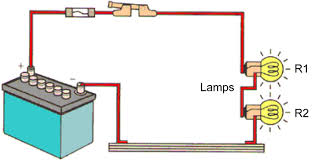
Description with Words: Three D-cells are placed in a battery pack to power a circuit containing three light bulbs.
Using the verbal description, one can acquire a mental picture of the circuit being described. This verbal description can then be represented by a drawing of three cells and three light bulbs connected by wires. Finally, the circuit symbols presented above can be used to represent the same circuit. Note that three sets of long and short parallel lines have been used to represent the battery pack with its three D-cells. And note that each light bulb is represented by its own individual resistor symbol. Straight lines have been used to connect the two terminals of the battery to the resistors and the resistors to each other.
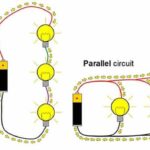
The above circuits presumed that the three light bulbs were connected in such a way that the charge flowing through the circuit would pass through each one of the three light bulbs in consecutive fashion. The path of a positive test charge leaving the positive terminal of the battery and traversing the external circuit would involve a passage through each one of the three connected light bulbs before returning to the negative terminal of the battery. But is this the only way that three light bulbs can be connected? Do they have to be connected in consecutive fashion as shown above? Absolutely not! In fact, example 2 below contains the same verbal description with the drawing and the schematic diagrams being drawn differently.
Example 2:
Description with Words: Three D-cells are placed in a battery pack to power a circuit containing three light bulbs.
Using the verbal description, one can acquire a mental picture of the circuit being described. But this time, the connections of light bulbs is done in a manner such that there is a point on the circuit where the wires branch off from each other. The branching location is referred to as anode. Each light bulb is placed in its own separate branch. These branch wires eventually connect to each other to form a second node. A single wire is used to connect this second node to the negative terminal of the battery.
These two examples illustrate the two common types of connections made in electric circuits. When two or more resistors are present in a circuit, they can be connected in series or in parallel. The remainder of Lesson 4 will be devoted to a study of these two types of connections and the effect that they have upon electrical quantities such as current, resistance and electric potential. The next part of Lesson 4 will introduce the distinction between series and parallel connections.
Check Your Understanding
1. Use circuit symbols to construct schematic diagrams for the following circuits:
a. A single cell, light bulb and switch are placed together in a circuit such that the switch can be opened and closed to turn the light bulb on.
See Answer

b. A three-pack of D-cells is placed in a circuit to power a flashlight bulb.
See Answer

c. See Answer See Answer | d. See Answer See Answer  |

 2. Use the concept of conventional current to draw an unbroken line on the schematic diagram at the right that indicates the direction of the conventional current. Place an arrowhead on your unbroken line.
See Answer
 The conventional current in the external circuit is the direction that a positive charge would move. It is directed from the positive terminal to the negative terminal. The positive terminal of a cell is the long line and the negative terminal is the short line. If there is a two-cell battery, then the long line on the end is the positive terminal of the battery. The short line on the opposite end is the negative terminal of the battery.