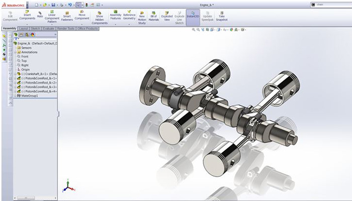
1) Explain what is SolidWorks?
SolidWorks is a computer aided design tool or software that runs on Microsoft Windows.
2) List out the major difference between the AutoCAD and SolidWorks?
The significant difference between the SolidWorks and AutoCAD is that
- AutoCAD was designed and developed as a 2D package and later evolved into a 3D package while SolidWorks is developed as 3D
3) Explain how you can insert a reference image in SolidWorks?
To add a reference image in SolidWorks follow these steps
- On the front plane open a new sketch
- Draw some reference geometry to help in sizing and positioning of the image
- Now to insert an image, go to -> Tools -> Sketch Picture
- Choose the image you want to insert and tap on “Open”
- Once the image gets inserted use the command box on the left of the panel, to adjust the size of the image.
4) List out the major or basic components of FeatureManager design tree?
The basic components of FeatureManager design tree includes
- Part
- Subassembly
- Flexible Subassembly
5) Explain how you can engrave text to part in SolidWorks?
To engrave text in SolidWorks you have to
- Once you have created the parts or your design ready in SolidWorks you have to go to main menu bar
- Under main menu bar -> Select tools
- Tools -> click on Sketch Entities
- Sketch Entities -> Text
- Input the text into the text box
- To change the font – uncheck the use document font and set the font type and size
- To engrave the text click Features -> tap on Extruded Cut -> now under direction 1 Blind, set the D1, and then click Isometric from the lower left view menu
6) Define what Groups is and Cut lists in SolidWorks?
- Groups: A group is a collection of the related segment in a structural member
- Cut lists: Under FeatureManager design tree, Cut list is an item that groups the same entities of a part together. It is available in parts that have sheet metal features or weldment.
7) Mention what does the weldments-pierce points indicates in SolidWorks?
In SolidWorks, the pierce point determines the location of the profile, related to the sketch segment used to form the structural member.
8) From where you can access SolidWorks API?
SolidWorks API is a com programming interface to the SolidWorks software. To access the API, you to go to Help -> API Help Topics.
9) Mention what all things included in Build Check Tools?
Inside Build Check Tools, all these checks tool are included
- Document Checks
- Annotation Checks
- Drawing Document Checks
- Dimension Checks
- Part Document Checks
- Assembly Document Checks
- Feature Checks
10) Mention what are two main modes for design studies in SolidWorks?
The two main modes for running a Design Study includes
- Evaluation: For each variable you specify discrete values and use sensors as constraints. The software executes the study using several combinations of the values and reports the output for each combination
- Optimization: For each variable you specify values, either as discrete values or as a range. You use sensors as constrains and as goals. The software executes iterations of the values and reports the maximum combination of values to meet your
11) Mention which command displays wireframe as solid surface with realistic textures and color?
Command “Shaded” will display the wireframe as solid surface with realistic textures and color.
12) Explain how you can create a Multi-body Sheet metal parts?
You can create a Multi-body sheet metal part by following steps
- In an existing sheet metal part, create a new bodies using commands for base flange, Insert bends, lofted bend and convert to sheet metals
- Then cut single sheet metal into multiple bodies
- Add one or more sheet metal, weldment or other bodies into an existing sheet metal part
- Copy a sheet metal body in a part by forming a circular or linear pattern, mirroring the body or by using the Move/Copy body command
13) Explain what is the use of CircuitWorks in SolidWorks?
In SolidWorks, CircuitWorks allows you to create 3D models from the file format created by most computer aided design systems.
14) Mention what is Bill of Materials or BOM in SolidWorks?
In SolidWorks, BOM creates bill automatically and cut lists for downstream manufacturing and purchasing operations.
15) Mention what are the two application in SolidWorks that checks the environmental impact or sustainability of parts created in SolidWorks?
The two application that checks the environmental impact or sustainability includes
- SolidWorks Sustainability Xpress
- SolidWorks Sustainability
16) Explain how you can add sustainability data to a custom material?
To add sustainability data to a custom material you have to
- Go to FeatureManager design tree, right click Material, and select Edit Material and tap on Edit Material
- Select the custom material in the material dialog box from the left panel
- Beside sustainability on the properties tab, choose Select
- Choose the material that is most similar to your custom material in the match sustainability information dialog box
- Click OK– the linked material will appear in Sustainability
- Click apply and then close
17) Explain how SolidWorks routed system works?
SolidWorks routed system is an add-in for creating piping and tubing routes and for creating electrical routes such as wiring harnesses.
18) Mention what does SolidWorks Utilities provides?
SolidWorks utilities provides nine categories of functionality
- Compare Geometry: It allows you to compare what geometry is different between two designs using Geometry comparison, View synchronization or Face synchronization
- Compare Features: It differentiate between two models and how they are different in their designs and color-codes
- Compare Document: It enables you to compare properties between two SolidWorks document
- Feature Paint: It allows you to implement existing feature attributes and parameters from one feature to another
- Geometry Analysis: It enables you to identify the problematic imported geometry in a part based on user-specific parameters like minimum silver face size,
- Power Select: It helps you to select loops, faces, edges and features based on geometric criteria
- Power Editing: It helps you to locate, manipulate and change features within a model according to their parameters
- Thickness Analysis: It provides an analysis tool to find thin and thick regions in part documents
- Simplify Geometry: It helps you to streamline parts, assembly documents and create simplified configurations automatically


