CATIA software is a multi-platform software suite for computer-aided design, computer-aided manufacturing, computer-aided engineering, PLM and 3D, developed by the French company Dassault Systèmes.Let’s Take a look at the basics of CATIA V5 in this article.
1: Introduction
INTRODUCTION TO CAD:
Computer Aided Design-CAD is defined the use of information technology (IT) in the Design process. A CAD system consists of IT hardware (H/W), specialized software (S/W) (depending on the area of application) and peripherals, which in certain applications are quite specialized. The core of a CAD system is the S/W, which makes use of graphics for product representation; databases for storing the product model and drives the peripherals for product presentation it does not change the nature of the design process but as the name states it aids the product designer. The role of the CAD is in aiding him/her by providing:
Accurately generated and easily modifiable graphical representation of the product. The user can nearly view the actual product on screen, make any modifications to it, and present his/her ideas on screen without any prototype, especially during the early stages of the design process.
Perform complex design analysis in short time. Implementing Finite Elements Analysis methods, the user can perform: Static, Dynamic and Natural Frequency analysis, Heat transfer analysis, Plastic analysis, Fluid flow analysis, Motion analysis, Tolerance analysis, Design optimization.
Record and recall information with consistency and speed. The use of Product Data Management (PDM) systems can store the whole design and processing history of a certain product, for future reuse and upgrade.
COVENTIONAL Vs MODERN DESIGN PROCESS
DESIGN PRODUCT CYCLE & CAD/CAM PROCESS:
INTRODUCTION TO CATIA V5
CATIA (an acronym of computer aided three-dimensional interactive application) developed by the French company Dassault Systèmes.
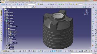
CATIA INTERFACE(GUI)
SPECIFICATION TREE
MOUSE CONTROLS
VIEW TOOLBAR
OTHER COMMONLY USED TOOLS:
2: Sketcher Module
The Sketcher workbench is a set of tools that helps you create and constrain 2D geometries. Features (pads, pockets, shafts, etc…) may then be created solids or modifications to solids using these 2D profiles. You can access the Sketcher workbench in many ways. Two simple ways are by using the top pull down menu (Start – Mechanical Design – Sketcher), or by selecting the Sketcher icon. When you enter the sketcher, CATIA requires that you choose a plane to sketch on. You can choose this plane either before or after you select the Sketcher icon. To exit the sketcher, select the Exit Workbench icon.
The Sketcher workbench contains the following standard workbench specific toolbars.
• Profile toolbar: The commands located in this toolbar allow you to create simple geometries (rectangle, circle, line, etc…) and more complex geometries (profile, spline, etc…).
• Operation toolbar: Once a profile has been created, it can be modified using commands such as trim, mirror, chamfer, and other commands located in the Operation toolbar.
• Constraint toolbar: Profiles may be constrained with dimensional (distances, angles, etc…) or geometrical (tangent, parallel, etc…) constraints using the commands located in the Constraint toolbar.
• Sketch tools toolbar: The commands in this toolbar allow you to work in different modes which make sketching easier.

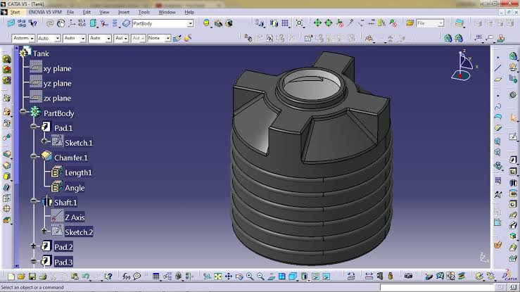
3: Part Design Module
Part design environment is used to create 3D models from the basic 2D sketches created in sketcher environment.
Some of the commands in workbench explained below
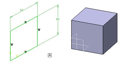
PAD command
In most CAD software, the equivalent of this is called EXTRUDE, but in CATIA we call it PAD. This command adds material in the third direction, a direction other than the sketch.
POCKET command
The POCKET commands somehow the opposite of PAD command. It simply helps remove geometry belonging to an already create part. On the figure below the POCKET command is helping to create the cylinder hole in the middle of the cube.
SHAFT command
It is Like revolve command in other CAD software, the SHAFT command is mostly used to make shaft like parts. It requires an axis, around which the sketch will be revolved.
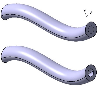
RIB command
This command which is usually known as SWEEP is called RIB IN CATIA. It adds material along a guide curve. RIB is used to make components like springs, pipes etc.
SLOT command
SLOT removes the material along a guide curve. Here is an example of slot. While using SLOT, I have used the same guide curve that was used for RIB. This ensures that the cross section will be uniform throughout.


4: Assembly Module
Assembly environment is used to provide mating to two or more part models to from complete assembly
We have two approaches in assembly
Top -down approach Bottom -up approach
entire design structure will be created in product environment in Top – down approach whereas in bottom – up parts will be created separately and will be mated using mating or constraint tools.

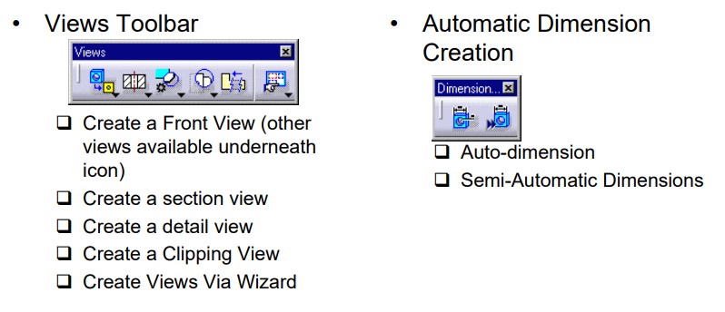
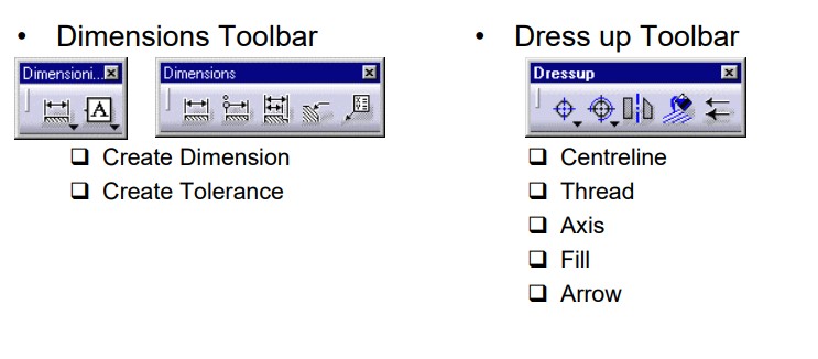
5: Drafting Module
Drafting is a process of generating 2D machine drawing for the 3D part models to send it to the manufacturer’s.
Catia drafting is of two types
1.Interactive Drafting
2. Generative Drafting