Flow of metal powders is determined by standard methods developed by ASTM and MPIF. Flow rate is the time required for a powder sample of a standard weight (50 g) to flow under atmospheric conditions through a funnel into the cavity of a container or mold. A determination of the flow rate of a powder is important in high-volume manufacturing, which depends on rapid, uniform, consistent filling of the die cavity. Poor flow characteristics cause slow and nonuniform press feeding and difficulty in ensuring even fills of the die cavity.
Before a powder is used in production, its flow characteristics must be known because some compacting tools require a free-flowing powder, while others can be used with a relatively poor-flowing powder. The term free-flowing refers to those physical properties of a powder–such as composition, particle fineness, and particle shape–that permit the powder to flow readily into the die cavity.
If a compacting tool is designed to handle a free-flowing powder, the use of a poor-flowing powder will necessitate modification. Compacting press manufacturers provide modified hopper designs and feeding shoe arrangements to accommodate finer, poor-flowing powders such as tungsten, molybdenum, or lighter aluminum powders.
The flow of powder from the feeding shoe into the die cavity can be increased by tapping or by changing the design of the filling device. These factors, however, are not taken into consideration in conventional flow rate test procedures, which consist of determining the time required for a given weight or volume of powder to flow through a standardized funnel-shaped cup with a small orifice at the bottom.
The following sections briefly review flow-rate test methods and variables that affect flow rate. Additional coverage is available in Ref 9, 10, 11, 12, 13, 14, 15, 16, 17, 18, 19, 20, and 21.
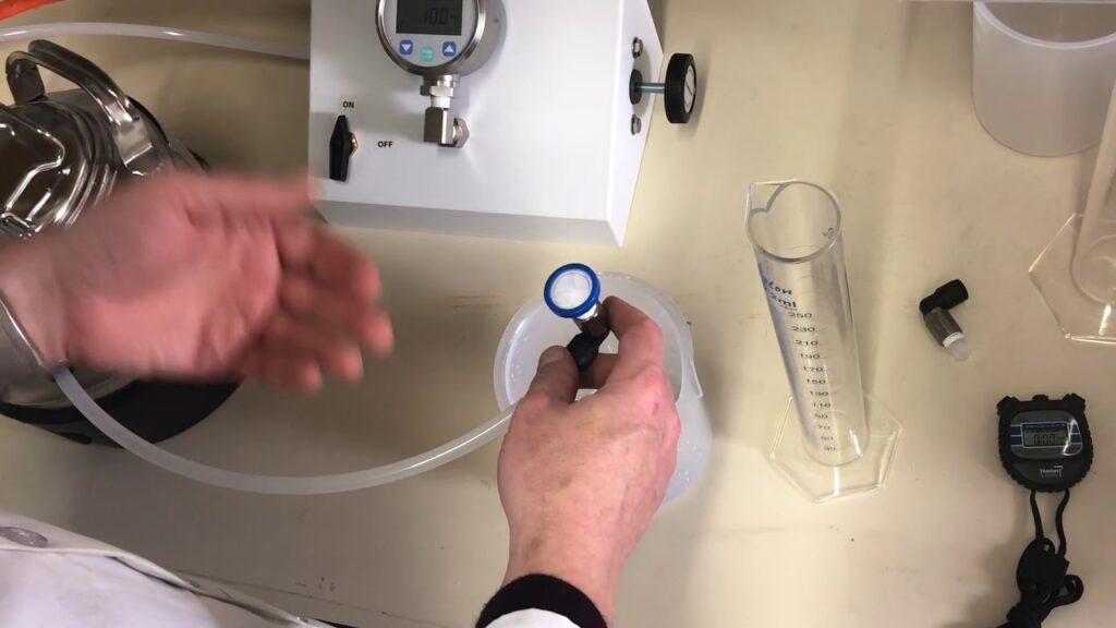
Hall Flowmeter. The device most commonly used for measuring flow rate is the Hall flowmeter (Fig. 15a), taken from ASTM B 213 and MPIF 3 (equivalent standards include ISO 4490, Japanese standard JIS 7-2502-1966, and German standard 82-69). The test equipment consists of a funnel with a calibrated hole 2.5 mm (0.1 in.) in diameter. The funnel, which is made of aluminum alloy 6061-T6, is supplied with a smooth finish to minimize wall friction.
With the help of a stopwatch and weighing balance, the flow rate of metal powders can be easily determined. A dry 50 g weight sample is transferred to the funnel, the orifice of which is covered with the operator’s fingertip. The stopwatch is started when the fingertip is removed and is stopped when the last quantity of the powder leaves the funnel. The flow rate (s/50 g) of the sample is reported as the elapsed time in seconds for 50 g of powder to flow through the orifice. A powder that does not flow through a 2.5 mm (0.1 in.) orifice Hall funnel, with or without an external impulse, is said to be a nonfree-flowing powder (as per ASTM B 213 and MPIF 3 method).
The Hall funnel is calibrated using a standardized powder (150-mesh Turkish emery grit), a sample of which is supplied with the equipment. The desired hole size is obtained by precisely honing a drilled hole until a satisfactory flow rate of emery powder is obtained.
A change in surface finish and the radius of the orifice (at the junction of the wall), buildup of material on the sidewalls of the orifice, or enlargement of the hole size due to continuous use can alter the standardization of the funnel. Verification of the calibration should be performed periodically by using the standardized emery powder. Calibration of the Hall funnel with Ballotini solid glass spheres, having particle size ranges of 0.090 to 0.102 mm (0.0036 to 0.004 in.) and 0.065 to 0.090 mm (0.0026 to 0.0036 in.) diameters, has yielded flow rates of 35.6 and 33.4 s/50 g, respectively.
The feed of powder to the die is handled on a volume basis. Thus, differences in apparent densities of powders can lead to considerable variations in the weight of material filling a given volume. A test for volumetric flow-rate determination is under investigation by ASTM. Table 6 lists the flow rates of metal powders for both weight and volume basis. The volumetric flow-rate tests were carried out using the Hall flowmeter. The data in Table 6 indicate that the readings for volumetric flow rate lie within a narrower range, as compared to the Hall flow rate.
| Table 6 Flow rate of metal powders through Hall and Carney funnelsMetal powder | Lubricant | Apparent density, g/cm3 | Flow rate of 50 g (2 oz) powder, s | Flow rate of 25 cm3 (1.5 in.3) powder through Half | Weight of 25(1.5 in.3) powder used in volumetric flow rate study | Calculated flow rate for 50 g (2 oz)powder based on | |||
| Material | Grade | Type | Addition, wt% | Hall funnel | Carney funnel | funnel, s | g oz | volumetric flow rates, s | |
| Iron | MP-35HD | Zinc stearate | None | 2.81 | 25.77 | 4.62 | 37.74 | 70.27 2.46 | 26.86 |
| Zinc | 0.25 | 3.12 | 23.37 | 4.16 | |||||
| stearate | |||||||||
| Zinc | 0.50 | 3.05 | 25.93 | 4.30 | |||||
| stearate | |||||||||
| Zinc | 0.75 | 3.02 | 26.80 | 4.41 | |||||
| stearate | |||||||||
| Zinc | 1.00 | 3.00 | 27.57 | 4.59 | 40.55 | 74.52 2.61 | 27.21 | ||
| stearate | |||||||||
| Iron | MH-100 | Zinc stearate | None | 2.48 | 30.14 | 5.26 | 38.61 | 62.06 2.17 | 31.11 |
| Zinc | 0.25 | 2.97 | 23.23 | 4.14 | |||||
| stearate | |||||||||
| Zinc | 0.50 | 2.93 | 26.39 | 4.47 | |||||
| stearate | |||||||||
| Zinc | 0.75 | 2.86 | 28.97 | 4.80 | |||||
| stearate | |||||||||
| Zinc | 1.00 | 2.87 | 30.42 | 5.12 | 42.20 | 71.31 2.50 | 29.59 | ||
| stearate | |||||||||
| Iron | A-Met 1000 | Zinc stearate | None | 2.94 | 26.24 | 4.34 | 39.16 | 73.91 2.59 | 26.49 |
| Zinc | 0.25 | 3.27 | 23.89 | 4.04 |
| stearate | ||||||||||
| Zinc | 0.50 | 2.98 | 28.30 | 4.55 | ||||||
| stearate | ||||||||||
| Zinc | 0.75 | 3.18 | 25.46 | 4.41 | ||||||
| stearate | ||||||||||
| Zinc | 1.00 | 3.18 | 25.58 | 4.45 | 41.70 | 79.57 | 2.78 | 26.20 | ||
| stearate | ||||||||||
| Stainless steel | 304-L | Lithium stearate | None | 2.61 | 30.62 | 4.92 | 39.65 | 65.45 | 2.29 | 30.29 |
| Lithium | 0.50 | 3.08 | 29.43 | 4.80 | ||||||
| stearate | ||||||||||
| Lithium | 0.75 | 3.01 | 33.20 | 5.42 | ||||||
| stearate | ||||||||||
| Lithium | 1.00 | 3.02 | 37.51 | 6.13 | 59.89 | 75.54 | 2.64 | 39.64 | ||
| stearate | ||||||||||
| Premix bronze | 5099 | Stearic | None | 2.96 | 21.68 | 3.99 | 32.69 | 74.92 | 2.62 | 21.82 |
| (90% Cu-10% | acid | |||||||||
| Sn) | Stearic acid | 0.25 | 3.54 | 24.01 | 5.17 | |||||
| Stearic | 0.50 | 3.54 | 24.66 | 5.38 | ||||||
| acid | ||||||||||
| Stearic | 0.75 | 3.42 | 27.91 | 5.24 | 49.84 | 85.68 | 3.0 | 29.08 | ||
| acid | ||||||||||
| Stearic | 1.00 | 3.38 | 34.75 | 7.20 | ||||||
| acid | ||||||||||
| Brass | B-126 | Lithium stearate | None | 2.89 | 33.26 | 5.51 | 48.56 | 72.67 | 2.54 | 33.41 |
| Lithium | 0.25 | 3.06 | 33.52 | 5.77 | ||||||
| stearate | ||||||||||
| Lithium | 0.50 | 3.14 | 38.70 | 6.38 | 64.01 | 78.25 | 2.74 | 40.90 | ||
| stearate | ||||||||||
| Aluminum | None | 1.19 | 66.43 | 39.23 | 29.73 | 1.04 | 65.97 |
Many factors can affect the accuracy of the results obtained with the Hall flowmeter, such as the moist finger of an operator (use of gloves can eliminate this effect), vibration of the surface on which the flowmeter is placed, humidity and temperature, condition of the sample, uniformity of the powder mix, and alternate use of the device for unlubricated and lubricated powders. Residual lubricant film left by a lubricated powder on the flow-meter wall or orifice can affect the subsequent flow test results of an unlubricated powder.
Other problems associated with its use include:
• Segregation of the mixture: Because only a small sample (50 g) is used, slight changes in particle size distribution can result in widely varying and misleading values.
• Limitedflowability information: If a powder is too cohesive to flow through the funnel, no information on the flowability of the powder can be determined. It has been estimated that up to 40 to 50% of all powder mixes used in the P/M industry will not flow through the Hall flowmeter.
• Meaningless results: Even if a powder does flow well, the value obtained (s/50 g) is not meaningful for many design problems. It cannot, for example, be extrapolated to predict limiting press speed, limiting flow rate through the feed hopper, or other rate-limiting phenomena.
The attempt to combine measurements of two material flow properties (minimum orifice size and flow rate) results in a method that does not measure either one very well (Ref 22).
Carney Funnel. Certain characteristics of some metal powders, such as particle shape and size distribution and lower specific gravity, may affect the powders to such an extent that they will not flow through the Hall funnel. In this case, the Carney funnel (Fig. 15b), which has the same dimensions as that of the Hall, except for a larger orifice diameter of 5 mm (0.2 in.), can be used to obtain a relative measure of the flowability of nonfree-flowing metal powders. The use of the Carney funnel, which is further described in ASTM B 417 and MPIF 28, is not a standardized test method in that there is no standard calibration procedure. However, it is used in industry to compare flow rates through a 5 mm (0.2 in.) orifice for a variety of materials. Because there is no correlating factor to relate the data obtained using the Carney funnel with that of the Hall, the user must establish an empirical relationship between the two methods.
Other Testing Methods. A number of other devices or methods for measuring the flow rates of metal powders have been developed. Efforts have been made to design test methods for powders that do not flow through either the Hall or Carney funnel and to reflect the shop floor conditions of these powders.
One method currently under consideration by the International Standards Organization determines the filling characteristics of metal powder into cavities of increasing sizes. A powder-filled shoe is slid back and forth once on the surface of a 40 mm (l.6 in.) thick plate (placed on a paper) into which bores with diameters of 5, 7, 10, 15, 20, 25, and 30 mm (0.2, 0.3, 0.4, 0.6, 0.8, 1.0, and 1.2 in.) have been drilled.
The plate is then lifted, and the powder that has fallen onto the paper from each of the seven die cavities is weighed. When the mass of the powder is divided by the volume of the respective cavity, the filling density for each cavity is obtained. The test provides the critical diameter, that is, the dividing line between cavity diameters which will be filled at a constant apparent density and those through which the powder may not flow at all or which may result in incomplete cavity fill.
In 1956, a second test method for determining the flow rate of metal powders that do not flow through the Hall funnel was developed by Chrysler Corporation as an internal standard. The test equipment consists of a powder shoe of 102 cm3 (6.2 in.3) in volume and a pivoted lever attached to the shoe at one end and to a cam follower at the other. A four-lobed cam is connected to a gearbox and is driven by a motor. A circular opening of 12.7 mm (0.5 in.) diam (with a 3.0 mm (0.12 in.) wide bar at center) drilled on a 2.4 mm (0.1 in.) thick metal plate acts as a die opening.
To conduct the test, the powder-filled shoe is moved back and forth over the opening four times. This is referred to as a one-cycle operation. The quantity of powder passing through the opening is collected on a balance pan and weighed. The test equipment simulates the action of a production press, and flow is measured in terms of the quantity of powder that passes through the opening in one filling cycle of a shoe.
In one production example, the normal range for a bronze powder mix was 80 to 95 g (2.8 to 3.3 oz) per cycle, whereas the data of all the lots ranged from 30 to 125 g (1 to 4 oz) per cycle of operation. The test method was used to check the flow of a production mix under conditions comparable to those encountered in the production presses. The test indicated the flowability of a powder mix accurately.
The die-filling operation of a production press can be simulated by a third test method in which actual bearing die cavities are used. For the production of bearings with varying wall thicknesses and complicated shapes, the tool design should accommodate the variations in filling properties of the powder mixes. The following test procedure was found to be especially useful for complex powder mixes that may or may not flow through the Hall flowmeter.
The equipment consists of a powder shoe, which slides over a metal plate with a recessed cavity in which a series of cups (with or without core rods) can be fitted. The sizes of the resulting bearing-shaped cavities vary between 3.3 to 8.2 cm3 (0.2 to 0.5 in.3) in volume with wall thicknesses ranging from 1 to 3 mm (0.04 to 0.12 in.) and corresponding core rod diameters from 19 to 15 mm (0.8 to 0.6 in.) with a constant height of 45 mm (1.8 in.). A reference cavity of the same height is coreless, with a volume of 16 cm3 (1.0 in.3).
With the selected size of the bearing die in position, the powder shoe is mechanically traversed through the die (or cup) opening and back to the original position. The cup is then removed and weighed. The quantity of powder is divided by the total volume of the cup, and the fill density of the powder is calculated. The process is repeated for the remaining die sizes by changing the core rod inserts. The filling density of the reference cavity is always the highest and is designated 100 for a given sample. This value is decreased with a reduction in wall thickness.
Tests with iron, nickel, copper, tin, and Turkish emery grit indicate that the results are consistent. The powders tested either flowed into the cup or did not enter at all. By evaluating filling densities in different die sizes, the test provides meaningful information in designing tools for a production shop. This test method was used to study blending variables and yielded close agreement with the performance of the production presses. Unfortunately, the test is not simple and requires the use of precise equipment.