Servo Motor Control
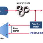
For understanding servo motor control let us consider an example of servomotor that we have given a signal to rotate by an angle of 45° and then stop and wait for further instruction. The shaft of the DC motor is coupled with another shaft called output shaft, with the help of gear assembly. This gear assembly is used to step down the high rpm of the motor’s shaft to low rpm at the output shaft of the servo system. 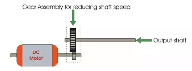
The voltage adjusting knob of a potentiometer is so arranged with the output shaft by means of another gear assembly, that during rotation of the shaft, the knob also rotates and creates an varying electrical potential according to the potentiometer.
This signal i.e. electrical potential is increased with angular movement of potentiometer knob along with the system shaft from 0° to 45°. This electrical potential or voltage is taken to the error detector feedback amplifier along with the input reference commends i.e. input signal voltage. 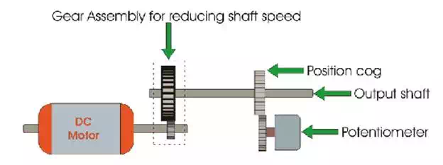
As the angle of rotation of the shaft increases from 0o to 45o the voltage from potentiometer increases. At 45° this voltage reaches to a value which is equal to the given input command voltage to the system. As at this position of the shaft, there is no difference between the signal voltage coming from the potentiometer and reference input voltage (command signal) to the system, the output voltage of the amplifier becomes zero. 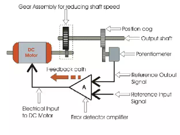
As per the picture given above the output electrical voltage signal of the amplifier, acts as input voltage of the DC motor. Hence, the motor will stop rotating after the shaft rotates by 45o. The motor will be at this rest position until another command is given to the system for further movement of the shaft in the desired direction. From this example we can understand the most basic servo motor theory and how servo motor control is achieved.
NB: Although in practical servo motor control system, instead of using simple potentiometer we use digital or analog position sensor encoder.
From this basic working principle of servo motor it can be concluded. The shaft of the servo is connected to a potentiometer. The circuitry inside the servo, to which the potentiometer is connected, knows the position of the servo. The current position will be compared with the desired position continuously with the help of an Error Detection Amplifier. If a mismatch is found, then an error signal is provided at the output of the error amplifier and the shaft will rotate to go the exact location required. Once the desired location is reached, it stops and waits.
Continuous Rotation Servo Motors
Continuous rotation servo motors are actually a modified version of what the servos are actually meant to do, that is, control the shaft position. The 360° rotation servos are actually made by changing certain mechanical connections inside the servo. However, a certain manufacturer like parallax sells these servos as well. With the continuous rotation servo you can only control the direction and speed of the servo, but not the position.
Two of the most popular Servo motor manufacturers are FUTABA and HITEC.