Servo Motor Working Principle
Before understanding the working principle of servo motor we should understand first the basic of servomechanism.
Servomechanism
A servo system mainly consists of three basic components – a controlled device, a output sensor, a feedback system.
This is an automatic closed loop control system. Here instead of controlling a device by applying the variable input signal, the device is controlled by a feedback signal generated by comparing output signal and reference input signal.
When reference input signal or command signal is applied to the system, it is compared with output reference signal of the system produced by output sensor, and a third signal produced by a feedback system. This third signal acts as an input signal of controlled device.
This input signal to the device presents as long as there is a logical difference between reference input signal and the output signal of the system. After the device achieves its desired output, there will be no longer the logical difference between reference input signal and reference output signal of the system. Then, the third signal produced by comparing theses above said signals will not remain enough to operate the device further and to produce a further output of the system until the next reference input signal or command signal is applied to the system. Hence, the primary task of a servomechanism is to maintain the output of a system at the desired value in the presence of disturbances.
Working Principle of Servo Motor
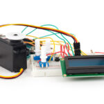
A servo motor is basically a DC motor(in some special cases it is AC motor) along with some other special purpose components that make a DC motor a servo. In a servo unit, you will find a small DC motor, a potentiometer, gear arrangement and an intelligent circuitry. The intelligent circuitry along with the potentiometer makes the servo to rotate according to our wishes. As we know, a small DC motor will rotate with high speed but the torque generated by its rotation will not be enough to move even a light load. This is where the gear system inside a servomechanism comes into the picture. The gear mechanism will take high input speed of the motor (fast) and at the output, we will get an output speed which is slower than original input speed but more practical and widely applicable.
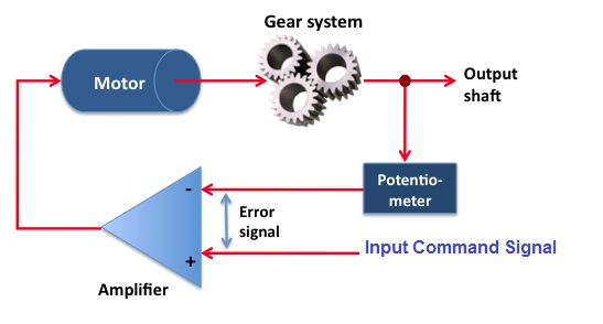
Say at initial position of servo motor shaft, the position of the potentiometer knob is such that there is no electrical signal generated at the output port of the potentiometer. This output port of the potentiometer is connected with one of the input terminals of the error detector amplifier. Now an electrical signal is given to another input terminal of the error detector amplifier. Now difference between these two signals, one comes from potentiometer and another comes from external source, will be amplified in the error detector amplifier and feeds the DC motor. This amplified error signal acts as the input power of the DC motor and the motor starts rotating in desired direction. As the motor shaft progresses the potentiometer knob also rotates as it is coupled with motor shaft with help of gear arrangement. As the position of the potentiometer knob changes there will be an electrical signal produced at the potentiometer port. As the angular position of the potentiometer knob progresses the output or feedback signal increases. After desired angular position of motor shaft the potentiometer knob is reaches at such position the electrical signal generated in the potentiometer becomes same as of external electrical signal given to amplifier. At this condition, there will be no output signal from the amplifier to the motor input as there is no difference between external applied signal and the signal generated at potentiometer. As the input signal to the motor is nil at that position, the motor stops rotating. This is how a simple conceptual servo motor works.