
Figure 1.1.3 Operations involved in design and manufacturing of a product
Today’s customers are demanding more variety and higher levels of flexibility in the products. Due to these demands and competition in the market, manufacturers are thriving to launch new/modified products to survive. It is reducing the product life as well as lead-time tomanufacture a product. It is therefore essential to automate the manufacturing and assembly operations of a product. There are various activities involved in the product manufacturing process. These are shown in figure 1.1.3. These activities can be classified into two groupsviz. design and manufacturing activities.
Mechatronics concurrently employs the disciplines of mechanical, electrical, control and computer engineering at the stage of design itself. Mechanical discipline is employed in terms of various machines and mechanisms, whereas electrical engineering as various electric primemovers viz. AC/DC, servo motors and other systems is used. Control engineering helps in the development of various electronics- based control systems to enhance or replace the mechanics of the mechanical systems. Computers are widely used to write various software’s to controlthe control systems; product design and development activities; materials and manufacturing resource planning, record keeping, market survey, and other sales related activities.
Using computer aided design (CAD) / computer aided analysis (CAE) tools, three- dimensional models of products can easily be developed. These models can then be analyzed and can be simulated to study their performances using numerical tools. These numerical tools are beingcontinuously updated or enriched with the real-life performances of the similar kind of products. These exercises provide an approximate idea about performance of the product/system to the design team at the early stage of the product development. Based on the simulation studies, the designs can be modified to achieve better performances. During the conventional design- manufacturing process, the design assessment is generally carried out after the production of first lot of the products. This consumes a lot of time, which leads to longer (in months/years) productdevelopment lead-time. Use of CAD–CAE tools saves significant time in comparison with that required in the conventional sequential design process.
CAD-CAE generated final designs are then sent to the production and process planning section. Mechatronics based systems such as computer aided manufacturing (CAM): automatic process planning, automatic part programming, manufacturing resource planning, etc. uses the designdata provided by the design team. Based these inputs, various activities will then be planned to achieve the manufacturing targets in terms of quality and quantity with in a stipulated time frame.
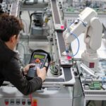
Mechatronics based automated systems such as automatic inspection and quality assurance, automatic packaging, record making, and automatic dispatch help to expedite the entire manufacturing operation. These systems certainly ensure a supply better quality, well packed and reliable products in the market. Automation in the machine tools has reduced the human intervention in the machining operation and improved the process efficiency and product quality. Therefore it is important to study the principles of mechatronics and to learn how to apply them in theautomation of a manufacturing system.
Mechatronics system
A system can be thought of as a box or a bounded whole which has input and output elements, and a set of relationships between these elements. Figure 1.1.4 shows a typical spring system. It has ‘force’ as an input which produces an ‘extension’. The input and output of this system followsthe Hooke’s law F = –kx, where F is force in N, x is distance in m and k is stiffness of the spring.

Figure 1.1.4 A spring-force system

Figure 1.1.5 Constituents of a mechatronics system
A Mechatronics system integrates various technologies involving sensors, measurement systems, drives, actuation systems, microprocessor systems and software engineering. Figure 1.1.5 shows the basic elements of a mechatronics system. Consider the example ofa simple spring-mass system as shown in figure
1.1.4. To replace the mechanics of this mechanical system with an equivalent mechatronics based system, we need to have the basic controlling element, a microprocessor. Microprocessor processes or utilizes the information gathered from the sensor system and generates the signals ofappropriate level and suitable kind (current or voltage) which will be used to actuate the required actuator viz. a hydraulic piston-cylinder device for extension of piston rod in this case. The microprocessor is programmed on the basis of the principle of Hooks’ Law. The schematic ofmicroprocessor based equivalent spring mass system is shown in figure
1.1.6.

Figure 1.1.6 Microprocessor based equivalent spring mass system
The input to the system is a force which can be sensed by suitable electro-mechanical sensors viz. piezo-electric device or strain gauges. These sensors generate either digital signals (0 or 1) or analogue signals (milli-volts or milli-amperes). These signals are then converted intoright form and are attenuated to a right level which can properly be used by the microprocessor to take generate the actuation signals. Various electronics based auxiliary devices viz. Analogue-to-Digital Converter (ADC), Digital-to-Analogue Converter (DAC), Op-amps, Modulators,Linearization circuits, etc. are used to condition the signals which are either received by the microprocessor from the sensors or are sent to the actuators from the microprocessor. This mechatronics based spring-mass system has the input signals in the digital form which are received from theADC and Piezo-electric sensor. The digital actuation signals generated by the microprocessors are converted into appropriate analogues signals. These analogue signals operate the hydraulic pump and control valves to achieve the desired displacement of the piston-rod.
In this course we will be studying in detail the various elements of a Mechtronics system (shown in figure 1.1.5) and their applications to manufacturing automation.
In the next lecture we will study the applications of Mechatronics in manufacturing engineering and in the subsequent lectures; above-mentioned elements will be discussed in detail.
Assignment 1: Study the product life cycle diagram and elaborate the various design and manufacturing activities for a product: four-wheel automobile (a passenger car) or a mobile cell phone.
Assignment 2: Identify a mechatronics system being used by you in your daily routine. Analyze its elements and state its importance in the functioning of that system.