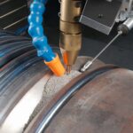
Gas metal-arc welding (GMAW) also called as metal inert-gas (MIG) welding, In Gas metal-arc welding process the weld area is shielded by an effectively inert atmosphere of argon, helium, carbon dioxide or various other gas mixtures. The consumable bare wire is fed automatically through a nozzle into the weld arc by a wire-feed drive motor. In addition to using inert shielding gases, de-oxidizers usually are present in the electrode metal itself in order to prevent oxidation.
The temperatures generated in Gas metal-arc welding are low, GMAW method is suitable only for thin sheets and sections of less than 6 mm, otherwise incomplete fusion may occur. GMAW operation is easy to perform is commonly used for welding ferrous metals in thin sections. Pulsed-arc systems are used for thin ferrous and nonferrous metals. GMAW process is used for welding most ferrous and nonferrous metals and is used extensively in the metal-fabrication industry. Because of the relatively simple nature of the process, the training of operators is easy. This process is versatile, quick, economical and welding productivity is double that of the Submerged-arc Welding process.
Equipment
To perform gas metal arc welding, the basic necessary equipment is a welding gun, a wire feed unit, a welding power supply, a welding electrode wire, and a shielding gas supply.
Welding gun and wire feed unit

GMAW torch nozzle cutaway image. (1) Torch handle, (2) Molded phenolic dielectric (shown in white) and threaded metal nut insert (yellow), (3) Shielding gas diffuser, (4) Contact tip, (5) Nozzle output face

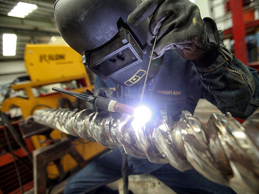
GMAW on stainless steel

Mig welding station
The typical GMAW welding gun has a number of key parts—a control switch, a contact tip, a power cable, a gas nozzle, an electrode conduit and liner, and a gas hose. The control switch, or trigger, when pressed by the operator, initiates the wire feed, electric power, and the shielding gas flow, causing an electric arc to be struck. The contact tip, normally made of copper and sometimes chemically treated to reduce spatter, is connected to the welding power source through the power cable and transmits the electrical energy to the electrode while directing it to the weld area. It must be firmly secured and properly sized, since it must allow the electrode to pass while maintaining electrical contact. On the way to the contact tip, the wire is protected and guided by the electrode conduit and liner, which help prevent buckling and maintain an uninterrupted wire feed. The gas nozzle directs the shielding gas evenly into the welding zone. Inconsistent flow may not adequately protect the weld area. Larger nozzles provide greater shielding gas flow, which is useful for high current welding operations that develop a larger molten weld pool. A gas hose from the tanks of shielding gas supplies the gas to the nozzle. Sometimes, a water hose is also built into the welding gun, cooling the gun in high heat operations.
The wire feed unit supplies the electrode to the work, driving it through the conduit and on to the contact tip. Most models provide the wire at a constant feed rate, but more advanced machines can vary the feed rate in response to the arc length and voltage. Some wire feeders can reach feed rates as high as 30 m/min (1200 in/min), but feed rates for semiautomatic GMAW typically range from 2 to 10 m/min (75 – 400 in/min)
Limitations:
§ Maximum size of electrodes used in Gas Metal-arc welding is less than or equal to 4mm.
§ Spatter loss in this process is high.
§ To keep the spatter loss within the limits of 10%, the maximum thickness of plate which can be joined by using MIG welding with single pass welding up to 30mm thickness only.