· The flow enters a three-dimensional impeller axially through an inlet duct. The impeller may be preceded by a row of inlet guide vanes.
· The impeller through its blades imparts velocity and pressure to the gas which flows in radial direction.
· The rise in pressure takes place due to the centrifugal action of the impeller and diverging passages of the downstream diffuser and / or volute
· Vaned or vaneless diffuser with volute are provided to convert kinetic energy at impeller exit into static pressure at compressor discharge.
· Centrifugal compressors are use d to produce large pressure ratios.
· A single stage centrifugal compressor may have typical pressure ratio of about 4:1. Some test compressors are designed for pressure ratio up to 8:1.
· Centrifugal compressors are suitable for low specific speed, high pressure ratio per stage and low mass flow rate applications.
· Based on application, the centrifugal compressors can be either single stage or multistage type.
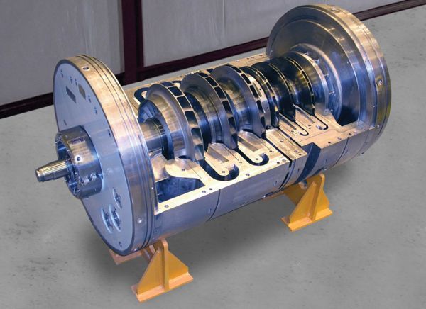
Components of a centrifugal compressor
· Impeller
· Diffuser
· Casing
· Shaft
Application of centrifugal compressor
· Gas turbine
· Turbocharger
· Process industry
![]() Gas compression
Gas compression
![]() Oxygen plants
Oxygen plants
![]() Instrument air
Instrument air