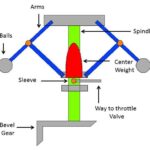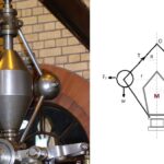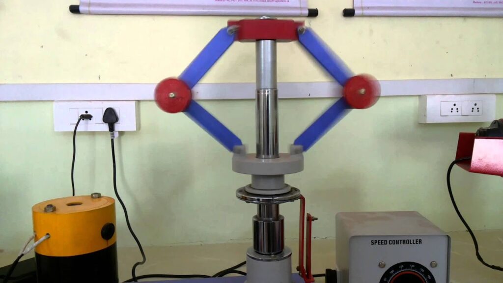
The simplest form of a centrifugal governor is a Watt governor, as shown in Fig. 5.2. It is basically a conical pendulum with links attached to a sleeve of negligible mass. The arms of the governor may be connected to the spindle in the following three ways :
1. The pivot P, may be on the spindle axis as shown in Fig. 5.2 (a).
2. The pivot P, may be offset from the spindle axis and the arms when produced intersect at O, as shown in Fig. 5.2 (b).
3. The pivot P, may be offset, but the arms cross the axis at O, as shown in Fig. 5.2 (c).


Fig. 5.2.
1. the centrifugal force (FC) acting on the ball,
2. the tension (T) in the arm, and
3. the weight (w) of the ball.
Taking moments about point O, we have

. . . (i)
When g is expressed in m/s2 and ω in rad/s, then h is in metres. If N is the speed in r.p.m., then

. . . (ii) Note : We see from the above expression that the height of a governor h, is inversely proportional toN2.Therefore at high speeds, the value of h is small. At such speeds, the change in the value of h corresponding to a small change in speed is insufficient to enable a governor of this type to operate the mechanism to give the necessary change in the fuel supply. This governor may only work satisfactorily at relatively low speeds i.e.from 60 to 80 r.p.m.
(1.) Calculate the vertical height of a Watt governor when it rotates at 60 r.p.m. Also find the change in vertical height when its speed increases to 61 r.p.m.
Solution:
Given :
N1 = 60 r.p.m.
N2 = 61 r.p.m.
Initial height
We know that initial height,

Change in vertical height
We know that final height,

Change in vertical height = h1 – h2 = 0.248 – 0.24 = 0.008 m = 8 mm