This valve has a combined safety arrangement against
a) high steam pressure in the boiler and
b) low water level in the boiler.
A commonly used high steam low water safety valve consists of two valves, namely valve ‘U’ and valve ‘V’ as shown in Fig. 29.4 (a). Under normal condition, the valve ‘U’ rests upon its valve seat and the valve ‘V’ rests on valve ‘U’ which act as seat for valve ‘V’.
When valve act as safety against high pressure steam in the boiler:
Construction:
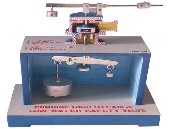
High steam and low water safety valve acts like a simple lever safety valve when it acts as safety against high steam pressure in the boiler. A lever ‘L1’,hinged at one end and loaded at the other end by a weight ‘W’, forces valve ‘U’ upon its seat through pivot ‘P’ as shown in Fig. 29.4 (a).
Operation:
· When the steam pressure in the boiler is under normal limit of working pressure: The upward force exerted by boiler steam on the valve ‘U’ is balanced by the downward force of lever system through pivot ‘P’. Under this condition, the valve ‘U’, having valve ‘V’ seated on it, remains on its seat tightly and the steam will not escape from the boiler as shown in Fig. 29.4 (a).
· When the steam pressure in the boiler exceeds above the normal limit of working pressure: The upward force exerted by boiler steam on the valve ‘U’ is overpowered the downward force of lever system. Under this condition, the valve ‘U’ having valve ‘V’ seated on it, lifts off automatically from its seat and escapes the steam through the passage between the valve ‘U’ and its valve seat to atmosphere as shown in Fig. 29.4 (b)until the pressure falls back to the normal working pressure.

Fig. 29.4. High Steam Low Water Safety Valve acts as safety against high pressure steam
When valve act as safety against low water level in the boiler:
Construction:
For prevention against low water level the high steam and low water safety valve is operated by a lever ‘L’ which is hinged at the fulcrum ‘F’ inside the boiler as shown in Fig. 29.4 (a). A weight ‘W1’ is attached to one end of the lever ‘L’ and a large floating earth ware ‘E’ to the other end. By hanging a dead weight ‘W2’ on the lower end of the spindle ‘S’ of valve ‘V’, the hemispherical shaped valve ‘V’ is forced downwards on valve ‘U’ which act as a seat for valve ‘V’. The knife edge ‘K’ of lever ‘L’ is provided to push collar ‘C’ of spindle ‘S’ for lifting valve ‘V’ from its seat.
Operation:
· When the water level in the boiler is at normal level: The floating earthen ware ‘E’ remains in water and whole level system ‘L’ with its weights is balanced. Under this condition, the valve ‘V’ is seated tightly on valve ‘U’ due to the downward force of dead weight ‘W2’ and the steam will not escape from the boiler as shown in Fig. 29.4 (a).
· When the water level in the boiler go down below the normal level: When the level of the water falls, the floating earthen ware ‘E’ is partly uncovered thus its weight increases due to decrease in buoyancy force on partly uncovered earthenware ‘E’. With this increase in weight of earthen ware ‘E’ as compared to Weight ‘W1’, the lever system ‘L’ becomes unbalanced and the earthen ware float ‘E’ moves in a downward direction. With this movement of lever the knife edge ‘K’ provided on lever push the collar C with the spindle and valve ‘V’ in the upward direction leaving valve ‘U’ on its seat and the steam gets the passage to escape to atmosphere between the valve ‘V’ and valve ‘U’ as shown in Fig. 29.5. The escaping of steam causes a loud noise as it passes through a specially constructed passage and alert the boiler attendant regarding low water level.

Fig. 29.5. High Steam Low Water Safety Valve in open position due to low water level
Uses:
This valve is used in internally fired boilers such as Lancashire and Cornish in which there is always a chance of overheating of the fire tubes.