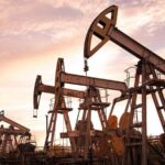
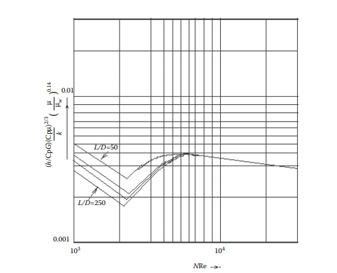
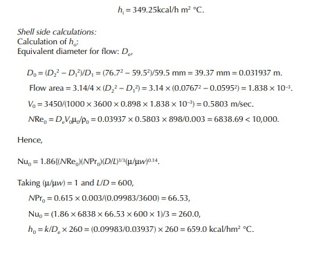
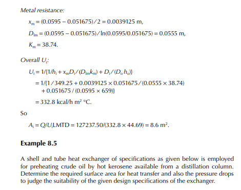
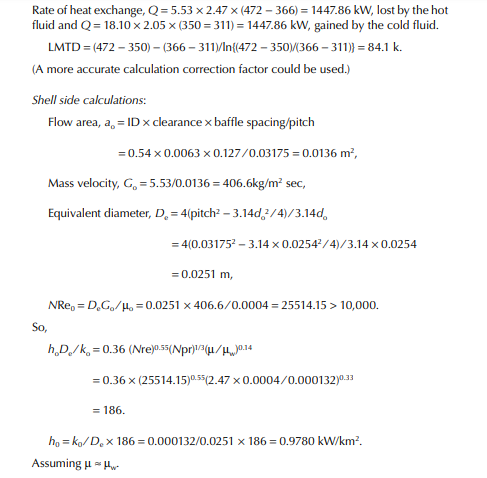
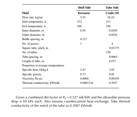
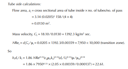
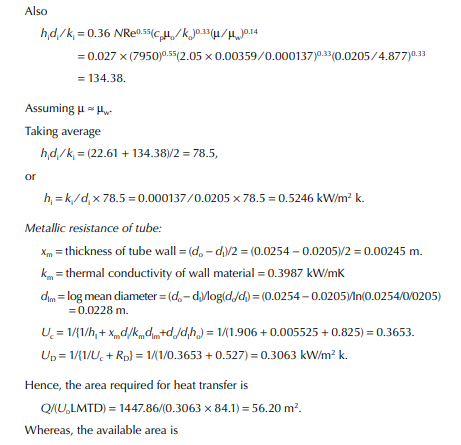
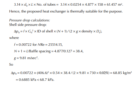
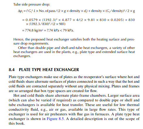
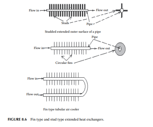
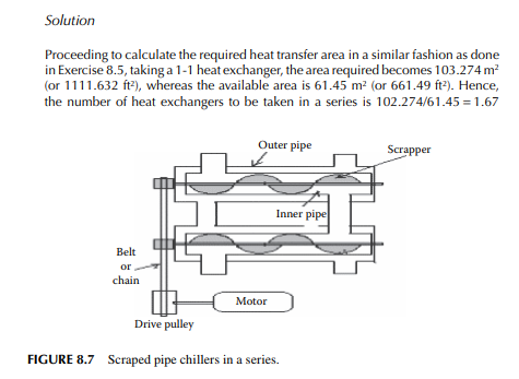
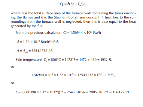
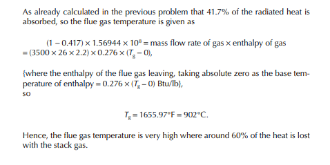
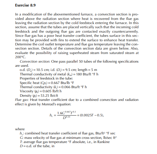
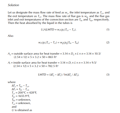
8.1 HEAT EXCHANGERS
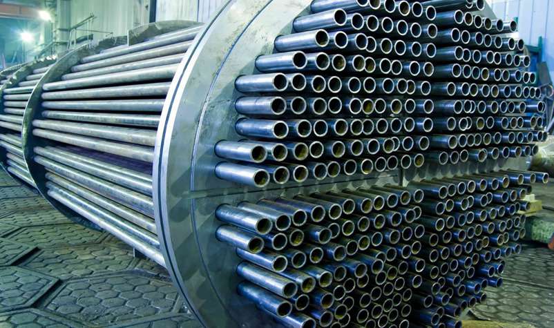
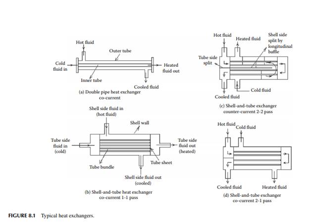
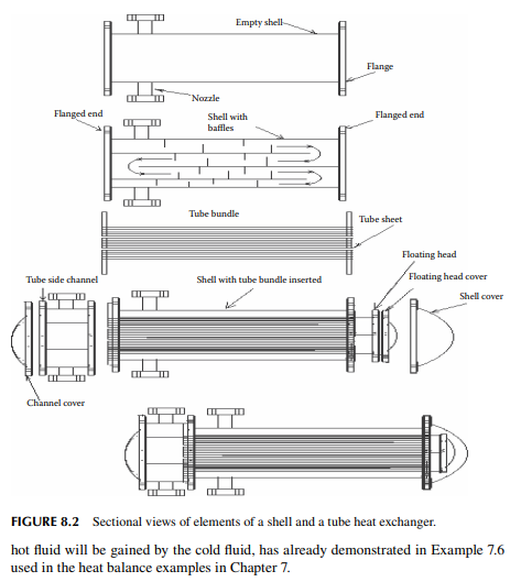
Heat exchanger equipment exchanges heat between a hot and a cold fl uid, i.e., cold fl uid is heated by hot fl uid without using any fi re or combustion. The most widely used heat exchangers transfer heat from hot to cold fl uid separated by a metallic surface. These types of heat exchangers are called recuperators, where the fl uids do not mix physically, but only the heat fl ows through the metallic wall surface. Double pipe and shell-and-tube exchangers are common recuperators. In a double pipe exchanger, one of the fl uids passes through an inner tube and the other fl uid passes through the annular space between the outer and inner tubes. A shell-and-tube heat exchanger consists of a bundle of tubes inside a large diameter outer tube or shell. One of the fl uids passes through the inner tubes in the bundle and the other fl uid passes through the annular space between the inner tubes and the shell. In both exchangers, fl uids may fl ow either in the opposite (countercurrent) or parallel direction (co-current). In fact, in the shelland-tube exchanger, fl ow paths are not exactly counter or co-current, rather they are crosscurrent, while the shell side fl uid fl ows partially at right angles to the tube side fl uid. The path equal to the length of the shell travelled by the tube side fl uid is called a tube side pass. If the fl uid enters at one end of the shell and leaves from the other end, then the number of tube passes is counted as one. If the other end of the tube is returned as a u-tube, the number of tube side passes will be two. Fluid in the shell side travelling a path equal to the length of the shell is similarly counted as a shell side pass.
Usually, circular plates, known as baffl es, occupy the annular space between the tubes and the shell, inducing turbulence to enhance heat transfer. Flow in the shell side takes place through an opening of the baffl es provided in a sequentially up and down position such that fl uid fl ows at right angles to the tubes. If there is no horizontal baffl e in the shell, fl uid will pass from one end to the other end, crossing the tube side, thus there will be one shell pass. If there is a single longitudinal baffl e (i.e., parallel to the tubes) placed exactly in the middle of the shell, two shell side passes will be generated. Both the double pipe and shell-and-tube exchangers with different tube and shell side passes are explained in Figures 8.1 and 8.2. Industrial heat exchangers may have more than two passes (either or both in the tube and shell sides) to enhance the high rate of heat transfer.
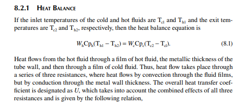
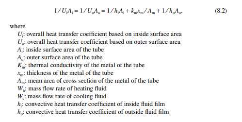
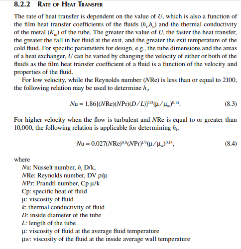
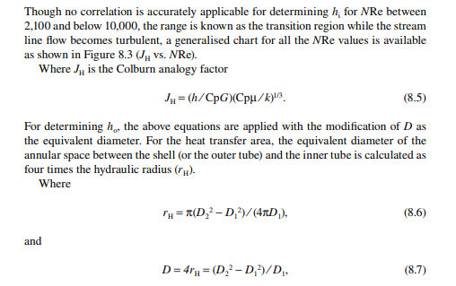
8.2 THEORY OF HEAT EXCHANGE
Heat fl ows from high temperature to low temperature according to the principle of thermodynamics. According to the law of conservation of energy, heat lost from the
8.8 PIPE-STILL FURNACE
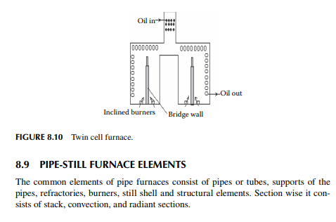
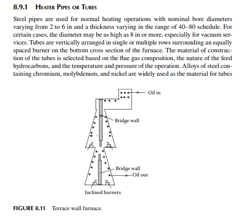
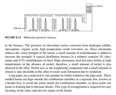
Tube-still heaters are used in petroleum and petrochemical plants for various purposes, such as crude distillation (atmospheric and vacuum), reboiling, and preheating of oil stocks, where heating is carried out for vaporisation purposes only. Tube-still furnaces are also used as reactors, as vis-breaking furnaces, coking furnaces, pyrolysis heaters in olefi n production, steam reformers for hydrogen production, etc. These are low temperature furnaces (as compared to furnaces used in metallurgical, ceramic, or cement plants), Where heat duty of burners vary from 0.5 to 100 million kcal/hr and temperature goes upto 1200°C. The pressure may be allowed as high as 10 MPa (100 atm, approximately). These furnaces are commonly housed in a cylindrical or rectangular box type refractory-lined steel casing supported on a steel structure above ground. The heater has a radiant section and a convection section. Feed fl owing through the pipes in the radiant section receives heat from the fl ames of the burning fuel from the burners. In the convection section, feed entering the furnace recovers heat from the hot fl ue gas leaving the radiant section. Various designs of such furnaces are available, such as helical coil type, vertical cylindrical, box type, twin cell type, terrace wall type, multisection pyrolysis type, etc. Typical tube-still furnaces are shown in Figures 8.9 through 8.12. A small duty furnace (
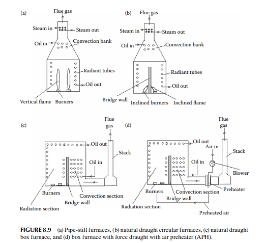
furnaces are built with a convection section at the top and a large radiant section at the bottom. Vertical box type furnaces also have the convection and radiation sections, but the cross section is rectangular instead of circular. In both types of vertical furnaces, burners are placed on the bottom of the furnace cross sections. Twin cell furnaces are designed to have two radiant boxes with a common convection section. Burners are inclined to heat the radiant walls such that overheating of the tubes is avoided for high temperature services. These are widely used as mild pyrolysis furnaces used in vis-breaking and coking. Terrace wall furnaces are used for steam reformer to generate hydrogen from methane or naphtha. Inclined burners are used to heat the refractory walls such that catalyst-fi lled tubes through which reactant hydrocarbons fl ow are uniformly heated at the highest temperature possible. Multizone furnaces are designed to have multiple pyrolysis sections to render cracking of the hydrocarbon feedstocks at the highest possible temperature in a very short time. These are used in olefi n production from ethane, naphtha, and even heavier fractions.
8.9.2 REFRACTORIES
The surface of the inside walls of the furnace is covered with refractory lining to refl ect most of the radiant heat generated by the fl ames. That is why these surfaces are called re-radiating surfaces. High alumina tiles or refractory lining containing as high as 97% alumina are commonly employed as re-radiating walls backed by high silica-alumina refractories. Insulating bricks with high porosity surround the refractory walls and protect the steel shell (which holds the refractories and the pipes’ structures and burners) from the high temperature of the furnace and loss of heat to the atmosphere.
8.9.3 BURNERS
Burners are devices by which the fuel and air mixture is brought in contact with a spark or ignition source and allow continuous combustion at a high temperature at its mouth. It contains a nozzle through which the fuel gas or vaporised liquid fuel emerges at a high velocity and causes air (primary air) to be entrained with the jet. Continuous combustion is sustained by the supply of secondary air in the combustion chamber. Heavy liquid fuel, which is not easily vaporisable, is atomised with dry steam by passing it through the nozzle of the burner. Liquid fuel and primary air are thus simultaneously entrained with the steam jet. Construction
of gas burners is different from oil burners due to the abovementioned different mechanisms of fi ring. The fl ame temperature depends on the heating value of the fuel and the rate of fi ring. A high turn down ratio ( as the ratio of maximum fi ring rate to the minimum fi ring rate) of fi ring must be maintained for a clean burner nozzle tip with a uniform fl ame of the desired diameter and length. (Turndown ratio is defi ned as the ratio of maximum fi ring rate to the minimum fi ring rate.) In the natural draught furnaces, primary and secondary air fl ow due to the difference of pressure of atmosphere and the hot gas within the furnace. This difference in pressure occurs owing to the difference between the atmospheric temperature and the furnace gas temperature. Burners of natural draught furnaces give longer fl ames and have the capacity to release heat in the range of 3–4 million kcal/h. The excess air requirement for these furnaces varies from 15%–20% with
8.9.4 CONVECTION ZONE
In this section, feedstock is heated by the hot fl ue gas leaving the radiant section below. A bank of large numbers of tubes are placed either countercurrently or crosscurrently to the upgoing fl ue gas stream. The tubes are connected with bends or in the form of coils in this section. Heat transfers from hot fl ue gas to the colder feedstock entering the convection zone. The diameter of the pipes is usually smaller than the radiant tubes. The outer tube surfaces have an extended surface with fi nned or studded type designs to promote convective heat transfer. Cold or preheated feed enters a bank or coils of tubes in the convection section. In this section, heat transfer between the feed fl owing through the tubes and the hot fl ue gas passing outside the tubes takes place mainly by convection. The fi lm heat transfer coeffi cients of the tube side fl uid and fl ue gas outside the tubes play the main role in heat transfer. These fi lm coeffi cients vary with the fl ow rates and the properties of the fl uids. The higher the fl ow rate or velocity either inside or outside the tubes, the more the heat transfer, and higher will be the temperature of feed stock exiting from the convection section. The conductivity, thickness, diameter, and surface area of the metallic tubes also infl uence the overall heat transfer coeffi cient. Calculations for the design of this section are similar to the design calculation for heat exchangers.
8.9.5 RADIANT SECTION
This section is the combustion chamber of the fuel in the presence of air and the heat is transferred to the tubes from the fl ames by radiation. An air and fuel mixture is burnt by a number of burners distributed over the cross section of the chamber to allow uniform heating without touching the surfaces of the tubes (i.e., without impinging the tube walls). Since the fl ame temperature is higher than 1000°C, the metal of the tube may be damaged due to impingement, such as local melting, oxidation or change in mechanical properties due to thermal shock, etc., and fi nally give way. The maximum allowable temperature of the surface of metallic pipes is restricted by the composition of the alloy used for construction. This temperature is also known as the allowable skin temperature of the metallic pipes. For very highduty heat transfer and temperature, it is necessary to use burners to heat the walls of the furnace, which then heat the tubes. Such indirect heat transfer is essential to avoid impingement of the fl ames on the tubes.
8.9.6 STACK OR CHIMNEY
The stack or chimney is an exhausting duct for the fl ue gas to the atmosphere. Combustion gases or fl ue gas contains carbon dioxide, carbon mono oxide, sulfur dioxide, water vapour, unburnt hydrocarbons, nitrogen, oxygen, etc. The temperature of the fl ue gas of most of the furnaces is maintained above 100°C so that no moisture is liquifi ed to cause acidic corrosion due to the presence of acid gases, such as sulfur dioxide, hydrogen sulfi de, mercaptans, etc., which are highly corrosive in the aqueous phase. The usual stack gas temperature is 120°C–150°C for the majority of furnaces, though it can be reduced by recovering heat in the convection section and also by preheating the combustion air in the forced draught furnaces. For such preheaters, the excess air requirement is reduced to 5% and, as a result, overall effi – ciency may be as high as 95%–98%. Depending on the ease of the contacting pattern of hot fl ue gas with the feedstock, combustion air, pressure, and the fl ow rate of fl ue gas, the stack may be placed on the top of the furnace or it may be on the ground or there may be single or multiple stacks. Dampers are also provided in the stack to adjust the draught of the furnace.
8.10 OPERATION OF A FURNACE
Furnace housing is placed above grade (i.e., above ground level) to provide enough space to facilitate lighting of burners, observation of fl ames through sight glasses, air suction registers for the ingress of combustion air, steam purging and inert gas purging of the radiant box, maintenance facilities for the burners, etc. An operating platform is provided above grade to allow opening and closing of the fuel and steam valves. Sight glasses are also provided to view inside the radiant section to monitor and adjust the fl ame on the burner tips. Dampers can also be operated from this platform. The steel shell wall temperature of the furnace must be maintained near ambient temperature to avoid thermal shocks to the operating personnel. Usually, the outside surface of the furnace need not be insulated as this may cause a rise in the steel shell wall temperature, which may damage the shell. Judicious insulation inside the shell by the bricks of low thermal conductivity encircling the refractory walls is suffi cient to bring down the steel shell temperature. Purging with low-pressure steam (snuffi ng steam) is essential before lighting the burners to avoid explosion due to the accumulated unburnt fuels from unsuccessful lighting events. Soot consisting of fi ne carbon particles, coke and ash
accumulate in the banks of tubes in the convection zone, thereby reducing the heat transfer. Hence, periodic soot blowing is essential for the convection zone. Steam or an air jet are blown over the tube banks to remove the soot by various means, e.g., manual or mechanical means.
8.11 DRAUGHT IN A FURNACE
The air column outside the furnace at ambient temperature has a higher pressure than the hot gas column inside the furnace chamber and, as a result of this pressure difference, air enters the combustion chamber through the air registers. This is called a natural draught and such a draught is maintained without any mechanical blowers. For forced draught furnaces, air is forced into the combustion chamber by blowers. A draught can also be made by suction of the fl ue gas by blowers and such a draught is called an induced draught. Both induced and forced draught systems may be used simultaneously in many furnaces to have good control over the draught and temperature of preheated air. Natural draught furnaces are cheaper, but yield poor effi ciency, high excess air requirement, and are prone to back fi ring during light up owing to poor control over the draught.
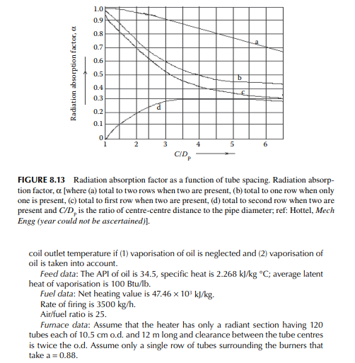
8.12 FURNACE DESIGN BY THE WILSON, LOBO AND HOTTEL METHOD
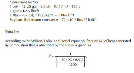
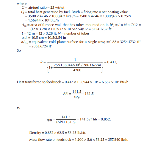
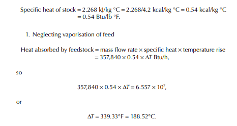
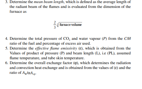
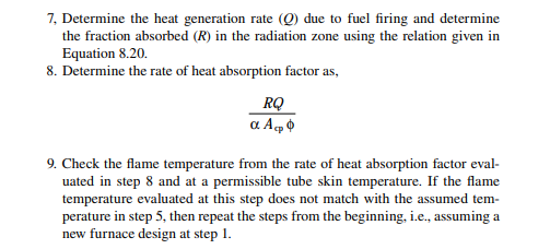
In this method, heat transfer is considered as combined radiation and convection. The overall relation for heat transfer is given as, according to the Wilson, Lobo, and Hottel equation, fraction (R) of heat generated by combustion that is absorbed by the tubes is given as
QUESTIONS
1. What are the basic differences between a heat exchanger and a furnace?
2. Defi ne the terms “recuperator,” “regenerator,” and “contact heat exchanger.”
3. Distinguish between a cooler and a condenser.
4. Describe the various elements of construction of a pipe-still heater.
5. Why are there two separate zones of convection and radiation in a furnace?
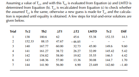
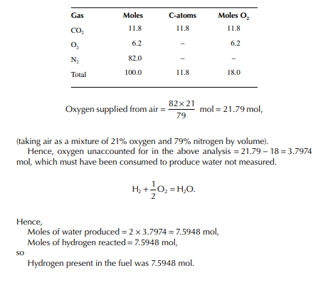
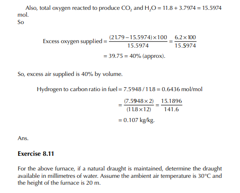
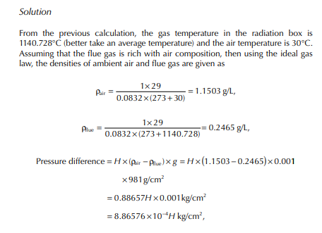
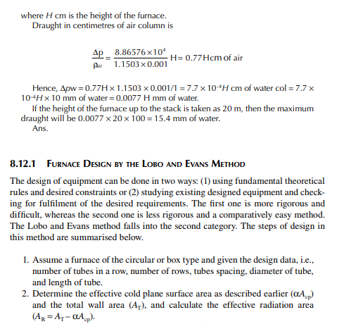
6. A furnace has to be used to heat crude oil before feeding into a distillation tower. Determine the coil outlet temperature of the crude oil from the following information. Crude throughput: 400 m3/h, API = 36, coil inlet temperature of 260°C at an average specifi c heat of 2.13 kJ/kg K. The number of pipes in the radiation zone is 180, the pipe o.d. is 2 inch, the length of 40 ft and placed with a clearance of 2.5 in from the centre of each pipe. The pipes are arranged in a single row circularly and vertically surrounding the burners distributed over the fl oor of the furnace. The fuel gas has a net heating value of 42,000 kJ/kg, the air to fuel ratio is 20 kg/kg, and the fuel fi ring rate is 2500 kg/h. Neglect the heat absorption in the convection zone.