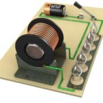
The magnetic flux through a circuit can be related to the current in that circuit and the currents in other nearby circuits, assuming that there are no nearby permanent magnets. Consider the following two circuits.

The magnetic field produced by circuit 1 will intersect the wire in circuit 2 and create current flow. The induced current flow in circuit 2 will have its own magnetic field which will interact with the magnetic field of circuit 1. At some point P, the magnetic field consists of a part due to i1 and a part due to i2. These fields are proportional to the currents producing them.
The coils in the circuits are labeled L1 and L2 and this term represents the self inductance of each of the coils. The values of L1 and L2 depend on the geometrical arrangement of the circuit (i.e. number of turns in the coil) and the conductivity of the material. The constant M, called the mutual inductance of the two circuits, is dependent on the geometrical arrangement of both circuits. In particular, if the circuits are far apart, the magnetic flux through circuit 2 due to the current i1 will be small and the mutual inductance will be small. L2 and M are constants.
We can write the flux, ![]() B through circuit 2 as the sum of two parts.
B through circuit 2 as the sum of two parts.
![]() B2 = L2i2 + i1M
B2 = L2i2 + i1M
An equation similar to the one above can be written for the flux through circuit 1.
![]() B1 = L1i1 + i2M
B1 = L1i1 + i2M
Though it is certainly not obvious, it can be shown that the mutual inductance is the same for both circuits. Therefore, it can be written as follows:
M1,2 = M2,1

How is mutual induction used in eddy current inspection?
In eddy current inspection, the eddy currents are generated in the test material due to mutual induction. The test probe is basically a coil of wire through which alternating current is passed. Therefore, when the probe is connected to an eddyscope instrument, it is basically represented by circuit 1 above. The second circuit can be any piece of conductive material.

When alternating current is passed through the coil, a magnetic field is generated in and around the coil. When the probe is brought in close proximity to a conductive material, such as aluminum, the probe’s changing magnetic field generates current flow in the material. The induced current flows in closed loops in planes perpendicular to the magnetic flux. They are named eddy currents because they are thought to resemble the eddy currents that can be seen swirling in streams.

The eddy currents produce their own magnetic fields that interact with the primary magnetic field of the coil. By measuring changes in the resistance and inductive reactance of the coil, information can be gathered about the test material. This information includes the electrical conductivity and magnetic permeability of the material, the amount of material cutting through the coils magnetic field, and the condition of the material (i.e. whether it contains cracks or other defects.) The distance that the coil is from the conductive material is called liftoff, and this distance affects the mutual-inductance of the circuits. Liftoff can be used to make measurements of the thickness of nonconductive coatings, such as paint, that hold the probe a certain distance from the surface of the conductive material.
It should be noted that if a sample is ferromagnetic, the magnetic flux is concentrated and strengthened despite opposing eddy current effects. The increase inductive reactance due to the magnetic permeability of ferromagnetic materials makes it easy to distinguish these materials from non ferromagnetic materials.
In the applet below, the probe and the sample are shown in cross-section. The boxes represent the cross-sectional area of a group of turns in the coil. The liftoff distance and the drive current of the probe can be varied to see the effects of the shared magnetic field. The liftoff value can be set to 0.1 or less and the current value can be varied from 0.01 to 1.0. The strength of the magnetic field is shown by the darkness of the lines.


