Basic Processing Steps of a Liquid Penetrant Inspection
Surface Preparation:
One of the most critical steps of a liquid penetrant inspection is the surface preparation. The surface must be free of oil, grease, water, or other contaminants that may prevent penetrant from entering flaws. The sample may also require etching if mechanical operations such as machining, sanding, or grit blasting have been performed. These and other mechanical operations can smear metal over the flaw opening and prevent the penetrant from entering.
Penetrant Application:
Once the surface has been thoroughly cleaned and dried, the penetrant material is applied by spraying, brushing, or immersing the part in a penetrant bath.
Penetrant Dwell:
The penetrant is left on the surface for a sufficient time to allow as much penetrant as possible to be drawn from or to seep into a defect. Penetrant dwell time is the total time that the penetrant is in contact with the part surface. Dwell times are usually recommended by the penetrant producers or required by the specification being followed. The times vary depending on the application, penetrant materials used, the material, the form of the material being inspected, and the type of defect being inspected for. Minimum dwell times typically range from five to 60 minutes. Generally, there is no harm in using a longer penetrant dwell time as long as the penetrant is not allowed to dry. The ideal dwell time is often determined by experimentation and may be very specific to a particular application.
Excess Penetrant Removal:
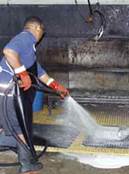
This is the most delicate part of the inspection procedure because the excess penetrant must be removed from the surface of the sample while removing as little penetrant as possible from defects. Depending on the penetrant system used, this step may involve cleaning with a solvent, direct rinsing with water, or first treating the part with an emulsifier and then rinsing with water. 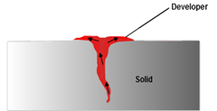
Developer Application:
A thin layer of developer is then applied to the sample to draw penetrant trapped in flaws back to the surface where it will be visible. Developers come in a variety of forms that may be applied by dusting (dry powdered), dipping, or spraying (wet developers).
Indication Development:
The developer is allowed to stand on the part surface for a period of time sufficient to permit the extraction of the trapped penetrant out of any surface flaws. This development time is usually a minimum of 10 minutes. Significantly longer times may be necessary for tight cracks.
Inspection:
Inspection is then performed under appropriate lighting to detect indications from any flaws which may be present.
Clean Surface:
The final step in the process is to thoroughly clean the part surface to remove the developer from the parts that were found to be acceptable.
Common Uses of Liquid Penetrant Inspection
Liquid penetrant inspection (LPI) is one of the most widely used nondestructive evaluation (NDE) methods. Its popularity can be attributed to two main factors: its relative ease of use and its flexibility. LPI can be used to inspect almost any material provided that its surface is not extremely rough or porous. Materials that are commonly inspected using LPI include the following:
● Metals (aluminum, copper, steel, titanium, etc.)
● Glass
● Many ceramic materials
● Rubber
● Plastics
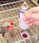
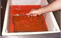
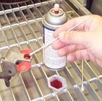
LPI offers flexibility in performing inspections because it can be applied in a large variety of applications ranging from automotive spark plugs to critical aircraft components. Penetrant materials can be applied with a spray can or a cotton swab to inspect for flaws known to occur in a specific area or it can be applied by dipping or spraying to quickly inspect large areas. In the image above, visible dye penetrant is being locally applied to a highly loaded connecting point to check for fatigue cracking.
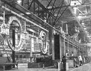
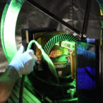
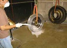
Penetrant inspection systems have been developed to inspect some very large components. In the image shown right, DC-10 banjo fittings are being moved into a penetrant inspection system at what used to be the Douglas Aircraft Company’s Long Beach, California facility. These large machined aluminum forgings are used to support the number two engine in the tail of a DC-10 aircraft.
Liquid penetrant inspection can only be used to inspect for flaws that break the surface of the sample. Some of these flaws are listed below:
● Fatigue cracks
● Quench cracks
● Grinding cracks
● Overload and impact fractures
● Porosity
● Laps
● Seams
● Pin holes in welds
● Lack of fusion or braising along the edge of the bond line
As mentioned above, one of the major limitations of a penetrant inspection is that flaws must be open to the surface.
Advantages and Disadvantages of Penetrant Testing
Like all nondestructive inspection methods, liquid penetrant inspection has both advantages and disadvantages. The primary advantages and disadvantages when compared to other NDE methods are summarized below.
Primary Advantages
● The method has high sensitivity to small surface discontinuities.
● The method has few material limitations, i.e. metallic and nonmetallic, magnetic and nonmagnetic, and conductive and nonconductive materials may be inspected.
● Large areas and large volumes of parts/materials can be inspected rapidly and at low cost.
● Parts with complex geometric shapes are routinely inspected.
● Indications are produced directly on the surface of the part and constitute a visual representation of the flaw.
● Aerosol spray cans make penetrant materials very portable.
● Penetrant materials and associated equipment are relatively inexpensive.
Primary Disadvantages
● Only surface breaking defects can be detected.
● Only materials with a relatively nonporous surface can be inspected.
● Precleaning is critical since contaminants can mask defects.
● Metal smearing from machining, grinding, and grit or vapor blasting must be removed prior to LPI.
● The inspector must have direct access to the surface being inspected.
● Surface finish and roughness can affect inspection sensitivity.
● Multiple process operations must be performed and controlled.
● Post cleaning of acceptable parts or materials is required.
● Chemical handling and proper disposal is required.
Penetrant Testing Materials
The penetrant materials used today are much more sophisticated than the kerosene and whiting first used by railroad inspectors near the turn of the 20th century. Today’s penetrants are carefully formulated to produce the level of sensitivity desired by the inspector. To perform well, a penetrant must possess a number of important characteristics. A penetrant must:
● spread easily over the surface of the material being inspected to provide complete and even coverage.
● be drawn into surface breaking defects by capillary action.
● remain in the defect but remove easily from the surface of the part.
● remain fluid so it can be drawn back to the surface of the part through the drying and developing steps.
● be highly visible or fluoresce brightly to produce easy to see indications.
● not be harmful to the material being tested or the inspector.

All penetrant materials do not perform the same and are not designed to perform the same. Penetrant manufactures have developed different formulations to address a variety of inspection applications.
Some applications call for the detection of the smallest defects possible and have smooth surfaces where the penetrant is easy to remove. In other applications, the rejectable defect size may be larger and a penetrant formulated to find larger flaws can be used. The penetrants that are used to detect the smallest defect will also produce the largest amount of irrelevant indications.
Penetrant materials are classified in the various industry and government specifications by their physical characteristics and their performance. Aerospace Material Specification (AMS) 2644, Inspection Material, Penetrant, is now the primary specification used in the USA to control penetrant materials.
Historically, Military Standard 25135, Inspection Materials, Penetrants, has been the primary document for specifying penetrants but this document is slowly being phased out and replaced by AMS 2644. Other specifications such as ASTM 1417, Standard Practice for Liquid Penetrant Examinations, may also contain information on the classification of penetrant materials but they are generally referred back to MIL-I-25135 or AMS 2644.
Penetrant materials come in two basic types. These types are listed below:
● Type 1 – Fluorescent Penetrants
● Type 2 – Visible Penetrants

Fluorescent penetrants contain a dye or several dyes that fluoresce when exposed to ultraviolet radiation. Visible penetrants contain a red dye that provides high contrast against the white developer background. Fluorescent penetrant systems are more sensitive than visible penetrant systems because the eye is drawn to the glow of the fluorescing indication.
However, visible penetrants do not require a darkened area and an ultraviolet light in order to make an inspection. Visible penetrants are also less vulnerable to contamination from things such as cleaning fluid that can significantly reduce the strength of a fluorescent indication.
Penetrants are then classified by the method used to remove the excess penetrant from the part. The four methods are listed below:
● Method A – Water Washable
● Method B – Post-Emulsifiable, Lipophilic
● Method C – Solvent Removable
● Method D – Post-Emulsifiable, Hydrophilic
Water washable (Method A) penetrants can be removed from the part by rinsing with water alone. These penetrants contain an emulsifying agent (detergent) that makes it possible to wash the penetrant from the part surface with water alone. Water washable penetrants are sometimes referred to as self-emulsifying systems. Post-emulsifiable penetrants come in two varieties, lipophilic and hydrophilic.
In post-emulsifiers, lipophilic systems (Method B), the penetrant is oil soluble and interacts with the oil-based emulsifier to make removal possible. Post-emulsifiable, hydrophilic systems (Method D), use an emulsifier that is a water soluble detergent which lifts the excess penetrant from the surface of the part with a water wash.
Solvent removable penetrants require the use of a solvent to remove the penetrant from the part.Penetrants are then classified based on the strength or detectability of the indication that is produced for a number of very small and tight fatigue cracks. The five sensitivity levels are shown below:
● Level ½ – Ultra Low Sensitivity
● Level 1 – Low Sensitivity
● Level 2 – Medium Sensitivity
● Level 3 – High Sensitivity
● Level 4 – Ultra-High Sensitivity
The major US government and industry specifications currently rely on the US Air Force Materials Laboratory at Wright-Patterson Air Force Base to classify penetrants into one of the five sensitivity levels.
This procedure uses titanium and Inconel specimens with small surface cracks produced in low cycle fatigue bending to classify penetrant systems. The brightness of the indication produced is measured using a photometer. The sensitivity levels and the test procedure used can be found in Military Specification MIL-I-25135 and Aerospace Material Specification 2644, Penetrant Inspection Materials.
An interesting note about the sensitivity levels is that only four levels were originally planned. However, when some penetrants were judged to have sensitivities significantly less than most others in the level 1 category, the ½ level was created. An excellent historical summary of the development of test specimens for evaluating the performance of penetrant materials can be found in the following reference.
Penetrants
The industry and military specifications that control penetrant materials and their use, all stipulate certain physical properties of the penetrant materials that must be met. Some of these requirements address the safe use of the materials, such as toxicity, flash point, and corrosiveness, and other requirements address storage and contamination issues. Still others delineate properties that are thought to be primarily responsible for the performance or sensitivity of the penetrants. The properties of penetrant materials that are controlled by AMS 2644 and MIL-I-25135E include flash point, surface wetting capability, viscosity, color, brightness, ultraviolet stability, thermal stability, water tolerance, and removability.
Emulsifiers
When removal of the penetrant from a defect due to over-washing of the part is a concern, a post-emulsifiable penetrant system can be used. Post-emulsifiable penetrants require a separate emulsifier to break the penetrant down and make it water-washable. Most penetrant inspection specifications classify penetrant systems into four methods of excess penetrant removal. These are listed below:
1. Method A: Water-Washable
2. Method B: Post-Emulsifiable, Lipophilic
3. Method C: Solvent Removable
4. Method D: Post-Emulsifiable, Hydrophilic
Method C relies on a solvent cleaner to remove the penetrant from the part being inspected. Method A has emulsifiers built into the penetrant liquid that makes it possible to remove the excess penetrant with a simple water wash. Method B and D penetrants require an additional processing step where a separate emulsification agent is applied to make the excess penetrant more removable with a water wash.
Lipophilic emulsification systems are oil-based materials that are supplied in ready-to-use form. Hydrophilic systems are water-based and supplied as a concentrate that must be diluted with water prior to use .
Lipophilic emulsifiers (Method B) were introduced in the late 1950’s and work with both a chemical and mechanical action. After the emulsifier has coated the surface of the object, mechanical action starts to remove some of the excess penetrant as the mixture drains from the part. During the emulsification time, the emulsifier diffuses into the remaining penetrant and the resulting mixture is easily removed with a water spray.
Hydrophilic emulsifiers (Method D) also remove the excess penetrant with mechanical and chemical action but the action is different because no diffusion takes place. Hydrophilic emulsifiers are basically detergents that contain solvents and surfactants.
The hydrophilic emulsifier breaks up the penetrant into small quantities and prevents these pieces from recombining or reattaching to the surface of the part. The mechanical action of the rinse water removes the displaced penetrant from the part and causes fresh remover to contact and lift newly exposed penetrant from the surface.
The hydrophilic post-emulsifiable method (Method D) was introduced in the mid 1970’s. Since it is more sensitive than the lipophilic post emulsifiable method it has made the later method virtually obsolete.
The major advantage of hydrophilic emulsifiers is that they are less sensitive to variation in the contact and removal time. While emulsification time should be controlled as closely as possible, a variation of one minute or more in the contact time will have little effect on flaw detectability when a hydrophilic emulsifier is used. However, a variation of as little as 15 to 30 seconds can have a significant effect when a lipophilic system is used.
Developers
The role of the developer is to pull the trapped penetrant material out of defects and spread it out on the surface of the part so it can be seen by an inspector. The fine developer particles both reflect and refract the incident ultraviolet light, allowing more of it to interact with the penetrant, causing more efficient fluorescence. The developer also allows more light to be emitted through the same mechanism. This is why indications are brighter than the penetrant itself under UV light. Another function that some developers perform is to create a white background so there is a greater degree of contrast between the indication and the surrounding background.
Developer Forms
The AMS 2644 and Mil-I-25135 classify developers into six standard forms. These forms are listed below:
1. Form a – Dry Powder
2. Form b – Water Soluble
3. Form c – Water Suspendable
4. Form d – Nonaqueous Type 1 Fluorescent (Solvent Based)
5. Form e – Nonaqueous Type 2 Visible Dye (Solvent Based)
6. Form f – Special Applications
The developer classifications are based on the method that the developer is applied. The developer can be applied as a dry powder, or dissolved or suspended in a liquid carrier. Each of the developer forms has advantages and disadvantages.
Dry Powder
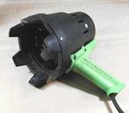
Dry powder developer is generally considered to be the least sensitive but it is inexpensive to use and easy to apply. Dry developers are white, fluffy powders that can be applied to a thoroughly dry surface in a number of ways. The developer can be applied by dipping parts in a container of developer, or by using a puffer to dust parts with the developer. Parts can also be placed in a dust cabinet where the developer is blown around and allowed to settle on the part.
Electrostatic powder spray guns are also available to apply the developer. The goal is to allow the developer to come in contact with the whole inspection area.
Unless the part is electrostatically charged, the powder will only adhere to areas where trapped penetrant has wet the surface of the part. The penetrant will try to wet the surface of the penetrant particle and fill the voids between the particles, which brings more penetrant to the surface of the part where it can be seen.
Since dry powder developers only stick to the area where penetrant is present, the dry developer does not provide a uniform white background as the other forms of developers do. Having a uniform light background is very important for a visible inspection to be effective and since dry developers do not provide one, they are seldom used for visible inspections. When a dry developer is used, indications tend to stay bright and sharp since the penetrant has a limited amount of room to spread.
Water Soluble

As the name implies, water soluble developers consist of a group of chemicals that are dissolved in water and form a developer layer when the water is evaporated away. The best method for applying water soluble developers is by spraying it on the part. The part can be wet or dry. Dipping, pouring, or brushing the solution on to the surface is sometimes used but these methods are less desirable. Aqueous developers contain wetting agents that cause the solution to function much like dilute hydrophilic emulsifier and can lead to additional removal of entrapped penetrant. Drying is achieved by placing the wet but well drained part in a recirculating, warm air dryer with the temperature held between 70 and 75°F. If the parts are not dried quickly, the indications will will be blurred and indistinct. Properly developed parts will have an even, pale white coating over the entire surface.
Water Suspendable
Water suspendable developers consist of insoluble developer particles suspended in water. Water suspendable developers require frequent stirring or agitation to keep the particles from settling out of suspension.
Water suspendable developers are applied to parts in the same manner as water soluble developers. Parts coated with a water suspendable developer must be forced dried just as parts coated with a water soluble developer are forced dried. The surface of a part coated with a water suspendable developer will have a slightly translucent white coating.
Nonaqueous
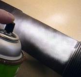
Nonaqueous developers suspend the developer in a volatile solvent and are typically applied with a spray gun. Nonaqueous developers are commonly distributed in aerosol spray cans for portability. The solvent tends to pull penetrant from the indications by solvent action. Since the solvent is highly volatile, forced drying is not required. A nonaqueous developer should be applied to a thoroughly dried part to form a slightly translucent white coating.
Special Applications
Plastic or lacquer developers are special developers that are primarily used when a permanent record of the inspection is required.
Preparation of Part

One of the most critical steps in the penetrant inspection process is preparing the part for inspection. All coatings, such as paints, varnishes, plating, and heavy oxides must be removed to ensure that defects are open to the surface of the part. If the parts have been machined, sanded, or blasted prior to the penetrant inspection, it is possible that a thin layer of metal may have smeared across the surface and closed off defects. It is even possible for metal smearing to occur as a result of cleaning operations such as grit or vapor blasting. This layer of metal smearing must be removed before inspection.
Contaminants
Coatings, such as paint, are much more elastic than metal and will not fracture even though a large defect may be present just below the coating. The part must be thoroughly cleaned as surface contaminates can prevent the penetrant from entering a defect. Surface contaminants can also lead to a higher level of background noise since the excess penetrant may be more difficult to remove.
Common coatings and contaminates that must be removed include: paint, dirt, flux, scale, varnish, oil, etchant, smut, plating, grease, oxide, wax, decals, machining fluid, rust, and residue from previous penetrant inspections.
Some of these contaminants would obviously prevent penetrant from entering defects, so it is clear they must be removed. However, the impact of other contaminants such as the residue from previous penetrant inspections is less clear, but they can have a disastrous effect on the inspection. Take the link below to review some of the research that has been done to evaluate the effects of contaminants on LPI sensitivity.
A good cleaning procedure will remove all contamination from the part and not leave any residue that may interfere with the inspection process. It has been found that some alkaline cleaners can be detrimental to the penetrant inspection process if they have silicates in concentrations above 0.5 percent. Sodium metasilicate, sodium silicate, and related compounds can adhere to the surface of parts and form a coating that prevents penetrant entry into cracks. Researchers in Russia have also found that some domestic soaps and commercial detergents can clog flaw cavities and reduce the wettability of the metal surface, thus reducing the sensitivity of the penetrant. Conrad and Caudill found that media from plastic media blasting was partially responsible for loss of LPI indication strength. Microphotographs of cracks after plastic media blasting showed media entrapment in addition to metal smearing.
It is very important that the material being inspected has not been smeared across its own surface during machining or cleaning operations. It is well recognized that machining, honing, lapping, hand sanding, hand scraping, grit blasting, tumble deburring, and peening operations can cause some materials to smear. It is perhaps less recognized that some cleaning operations, such as steam cleaning, can also cause metal smearing in the softer materials. Take the link below to learn more about metal smearing and its affects on LPI
Selection of a Penetrant Technique

The selection of a liquid penetrant system is not a straightforward task. There are variety of penetrant systems and developer types that are available for use, and one set of penetrant materials will not work for all applications. Many factors must be considered when selecting the penetrant materials for a particular application. These factors include the sensitivity required, materials cost, number of parts, size of area requiring inspection, and portability.
When sensitivity is the primary consideration for choosing a penetrant system, the first decision that must be made is whether to use fluorescent penetrant or visible dye penetrant. Fluorescent penetrants are generally more capable of producing a detectable indication from a small defect. Also, the human eye is more sensitive to a light indication on a dark background and the eye is naturally drawn to a fluorescent indication.
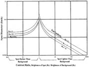
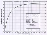
The graph below presents a series of curves that show the contrast ratio required for a spot of a certain diameter to be seen. The ordinate is the spot diameter, which was viewed from one foot. The abscissa is the contrast ratio between the spot brightness and the background brightness. To the left of the contrast ratio of one, the spot is darker than the background (representative of visible dye penetrant testing); and to the right of one, the spot is brighter than the background (representative of fluorescent penetrant inspection). Each of the three curves right or left of the contrast ratio of one are for different background brightness (in foot-Lamberts), but simply consider the general trend of each group of curves right or left of the contrast ratio of one. The curves show that for indication larger than 0.076 mm (0.003 inch) in diameter, it does not really matter if it is a dark spot on a light background or a light spot on a dark background. However, when a dark indication on a light background is further reduced in size, it is no longer detectable even though contrast is increased. Furthermore, with a light indication on a dark background, indications down to 0.003 mm (0.0001 inch) were detectable when the contrast between the flaw and the background was high.
From this data, it can be seen why a fluorescent penetrant offers an advantage over a visible penetrant for finding very small defects. Data presented by De Graaf and De Rijk supports this statement. They inspected “identical” fatigue cracked specimens using a red dye penetrant and a fluorescent dye penetrant. The fluorescent penetrant found 60 defects while the visible dye was only able to find 39 of the defects.
Ref: De Graaf, E. and De Rijk, P., Comparison Between Reliability, Sensitivity, and Accuracy of Nondestructive Inspection Methods, 13th Symposium on Nondestructive Evaluation Proceedings, San Antonio, TX, published by NTIAC, Southwest Research Institute, San Antonio, TX, April 1981, pp. 311-322.
Under certain conditions, the visible penetrant may be a better choice. When fairly large defects are the subject of the inspection, a high sensitivity system may not be warranted and may result in a large number of irrelevant indications. Visible dye penetrants have also been found to give better results when surface roughness is high or when flaws are located in areas such as weldments.
Since visible dye penetrants do not require a darkened area for the use of an ultraviolet light, visible systems are more easy to use in the field. Solvent removable penetrants, when properly applied, can have the highest sensitivity and are very convenient to use. However, they are usually not practical for large area inspection or in high-volume production settings.
Another consideration in the selection of a penetrant system is whether water washable, post-emulsifiable or solvent removable penetrants will be used. Post-emulsifiable systems are designed to reduce the possibility of over-washing, which is one of the factors known to reduce sensitivity. However, these systems add another step, and thus cost, to the inspection process.
Penetrants are evaluated by the US Air Force according to the requirements in MIL-I-25135 and each penetrant system is classified into one of five sensitivity levels. This procedure uses titanium and Inconel specimens with small surface cracks produced in low cycle fatigue bending to classify penetrant systems.
The brightness of the indications produced after processing a set of specimens with a particular penetrant system is measured using a photometer. A procedure for producing and evaluating the penetrant qualification specimens was reported on by Moore and Larson at the 1997 ASNT Fall Conference. Most commercially available penetrant materials are listed in the Qualified Products List of MIL-I-25135 according to their type, method and sensitivity level.
Visible dye and dual-purpose penetrants are not classified into sensitivity levels as fluorescent penetrants are. The sensitivity of a visible dye penetrant is regarded as level 1 and largely dependent on obtaining good contrast between the indication and the background.
Penetrant Application and Dwell Time
The penetrant material can be applied in a number of different ways, including spraying, brushing, or immersing the parts in a penetrant bath. The method of penetrant application has little effect on the inspection sensitivity but an electrostatic spraying method is reported to produce slightly better results than other methods. Once the part is covered in penetrant it must be allowed to dwell so the penetrant has time to enter any defect present.
There are basically two dwell mode options, immersion-dwell (keeping the part immersed

in the penetrant during the dwell period) and drain-dwell (letting the part drain during the dwell period). Prior to a study by Sherwin, the immersion-dwell mode was generally considered to be more sensitive but recognized to be less economical because more penetrant was washed away and emulsifiers were contaminated more rapidly. The reasoning for thinking this method was more sensitive was that the penetrant was more migratory and more likely to fill flaws when kept completely fluid and not allowed to lose volatile constituents by evaporation. However, Sherwin showed that if the specimens are allowed to drain-dwell, the sensitivity is higher because the evaporation increases the dyestuff concentration of the penetrant on the specimen. As pointed-out in the section on penetrant materials, sensitivity increases as the dyestuff concentration increases. Sherwin also cautions that the samples being inspected should be placed outside the penetrant tank wall so that vapors from the tank do not accumulate and dilute the dyestuff concentration of the penetrant on the specimen.
Penetrant Dwell Time
Penetrant dwell time is the total time that the penetrant is in contact with the part surface. The dwell time is important because it allows the penetrant the time necessary to seep or be drawn into a defect. Dwell times are usually recommended by the penetrant producers or required by the specification being followed. The time required to fill a flaw depends on a number of variables which include the following:
● The surface tension of the penetrant.
● The contact angle of the penetrant.
● The dynamic shear viscosity of the penetrant, which can vary with the diameter of the capillary. The viscosity of a penetrant in microcapillary flaws is higher than its viscosity in bulk, which slows the infiltration of the tight flaws.
● The atmospheric pressure at the flaw opening.
● The capillary pressure at the flaw opening.
● The pressure of the gas trapped in the flaw by the penetrant.
● The radius of the flaw or the distance between the flaw walls.
● The density or specific gravity of the penetrant.
● Microstructural properties of the penetrant.
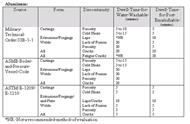
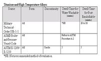
The ideal dwell time is often determined by experimentation and is often very specific to a particular application. For example, AMS 2647A requires that the dwell time for all aircraft and engine parts be at least 20 minutes, while ASTM E1209 only requires a five minute dwell time for parts made of titanium and other heat resistant alloys. Generally, there is no harm in using a longer penetrant dwell time as long as the penetrant is not allowed to dry.
The following tables summarize the dwell time requirements of several commonly used specifications. The information provided below is intended for general reference and no guarantee is made about its correctness. Please consult the specifications for the actual dwell time requirements.


Some Research Results on Dwell Time
An interesting point that Deutsch makes about dwell time is that if the elliptical flaw has a length to width ratio of 100, it will take the penetrant nearly ten times longer to fill than it will a cylindrical flaw with the same volume.
Lord and Holloway looked for the optimum penetrant dwell time required for detecting several types of defects in titanium. Both a level 2 post-emulsifiable fluorescent penetrant (Magnaflux ZL-2A penetrant and ZE-3 emulsifier) and a level 2 water washable penetrant (Tracer-Tech P-133A penetrant) were included in the study. The effect of the developer was a variable in the study and nonaqueous wet, aqueous wet, and dry developers were included. Specimens were also processed using no developer. The specimen defects included stress corrosion cracks, fatigue cracks and porosity. As expected, the researchers found that the optimal dwell time varied with the type of defect and developer used. The following table summarizes some of the findings.

Penetrant Removal Process

The penetrant removal procedure must effectively remove the penetrant from the surface of the part without removing an appreciable amount of entrapped penetrant from the defect. If the removal process extracts penetrant from the flaw, the flaw indication will be reduced by a proportional amount. If the penetrant is not effectively removed from the part surface, the contrast between the indication and the background will be reduced. As discussed in the Contrast Sensitivity Section, as the contrast increases, so does visibility of the indication.
Removal Method
Penetrant systems are classified into four methods of excess penetrant removal. These include the following:
1. Method A: Water-Washable
2. Method B: Post-Emulsifiable, Lipophilic
3. Method C: Solvent Removable
4. Method D: Post-Emulsifiable, Hydrophilic
Method C, Solvent Removable, is used primarily for inspecting small localized areas. This method requires hand wiping the surface with a cloth moistened with the solvent remover, and is, therefore, too labor intensive for most production situations. Of the three production penetrant inspection methods, Method A, Water-Washable, is the most economical to apply. Water-washable or self-emulsifiable penetrants contain an emulsifier as an integral part of the formulation. The excess penetrant may be removed from the object surface with a simple water rinse. These materials have the property of forming relatively viscous gels upon contact with water, which results in the formation of gel-like plugs in surface openings. While they are completely soluble in water, given enough contact time, the plugs offer a brief period of protection against rapid wash removal. Thus, water-washable penetrant systems provide ease of use and a high level of sensitivity.
When removal of the penetrant from the defect due to over-washing of the part is a concern, a post-emulsifiable penetrant system can be used. Post-emulsifiable penetrants require a separate emulsifier to breakdown the penetrant and make it water washable. The part is usually immersed in the emulsifier but hydrophilic emulsifiers may also be sprayed on the object. Spray application is not recommended for lipophilic emulsifiers because it can result in non-uniform emulsification if not properly applied. Brushing the emulsifier on to the part is not recommended either because the bristles of the brush may force emulsifier into discontinuities, causing the entrapped penetrant to be removed. The emulsifier is allowed sufficient time to react with the penetrant on the surface of the part but not given time to make its way into defects to react with the trapped penetrant. The penetrant that has reacted with the emulsifier is easily cleaned away. Controlling the reaction time is of essential importance when using a post-emulsifiable system. If the emulsification time is too short, an excessive amount of penetrant will be left on the surface, leading to high background levels. If the emulsification time is too long, the emulsifier will react with the penetrant entrapped in discontinuities, making it possible to deplete the amount needed to form an indication.
The hydrophilic post-emulsifiable method (Method D) is more sensitive than the lipophilic post-emulsifiable method (Method B). Since these methods are generally only used when very high sensitivity is needed, the hydrophilic method renders the lipophilic method virtually obsolete. The major advantage of hydrophilic emulsifiers is that they are less sensitive to variation in the contact and removal time. While emulsification time should be controlled as closely as possible, a variation of one minute or more in the contact time will have little effect on flaw detectability when a hydrophilic emulsifier is used. On the contrary, a variation of as little as 15 to 30 seconds can have a significant effect when a lipophilic system is used. Using an emulsifier involves adding a couple of steps to the penetrant process, slightly increases the cost of an inspection. When using an emulsifier, the penetrant process includes the following steps (extra steps in bold): 1. pre-clean part, 2. apply penetrant and allow to dwell, 3. pre-rinse to remove first layer of penetrant, 4. apply hydrophilic emulsifier and allow contact for specified time, 5. rinse to remove excess penetrant, 6. dry part, 7. apply developer and allow part to develop, and 8. inspect.
Rinse Method and Time for Water-Washable Penetrants
The method used to rinse the excess penetrant from the object surface and the time of the rinse should be controlled so as to prevent over-washing. It is generally recommended that a coarse spray rinse or an air-agitated, immersion wash tank be used. When a spray is being used, it should be directed at a 45° angle to the part surface so as to not force water directly into any discontinuities that may be present. The spray or immersion time should be kept to a minimum through frequent inspections of the remaining background level.
Hand Wiping of Solvent Removable Penetrants
When a solvent removable penetrant is used, care must also be taken to carefully remove the penetrant from the part surface while removing as little as possible from the flaw. The first step in this cleaning procedure is to dry wipe the surface of the part in one direction using a white, lint-free, cotton rag. One dry pass in one direction is all that should be used to remove as much penetrant as possible. Next, the surface should be wiped with one pass in one direction with a rag moistened with cleaner. One dry pass followed by one damp pass is all that is recommended. Additional wiping may sometimes be necessary; but keep in mind that with every additional wipe, some of the entrapped penetrant will be removed and inspection sensitivity will be reduced.
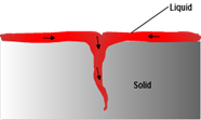
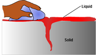
To study the effects of the wiping process, Japanese researchers manufactured a test specimen out of acrylic plates that allowed them to view the movement of the penetrant in a narrow cavity. The sample consisted of two pieces of acrylic with two thin sheets of vinyl clamped between as spaces. The plates were clamped in the corners and all but one of the edges sealed. The unsealed edge acted as the flaw. The clearance between the plates varied from 15 microns (0.00059055 inch) at the clamping points to 30 microns (0.0011811 inch) at the midpoint between the clamps. The distance between the clamping points was believed to be 30 mm (1.18 inch).
Although the size of the flaw represented by this specimen is large, an interesting observation was made. They found that when the surface of the specimen was wiped with a dry cloth, penetrant was blotted and removed from the flaw at the corner areas where the clearance between the plate was the least. When the penetrant at the side areas was removed, penetrant moved horizontally from the center area to the ends of the simulated crack where capillary forces are stronger. Therefore, across the crack length, the penetrant surface has a parabola-like shape where the liquid is at the surface in the corners but depressed in the center. This shows that each time the cleaning cloth touches the edge of a crack, penetrant is lost from the defect. This also explains why the bleedout of an indication is often largest at the corners of cracks.
Use and Selection of a Developer
The use of developer is almost always recommended. One study reported that the output from a fluorescent penetrant could be multiplied by up to seven times when a suitable powder developer was used. Another study showed that the use of developer can have a dramatic effect on the probability of detection (POD) of an inspection. When a Haynes Alloy 188, flat panel specimen with a low-cycle fatigue crack was inspected without a developer, a 90 % POD was never reached with crack lengths as long as 19 mm (0.75 inch). The operator detected only 86 of 284 cracks and had 70 false-calls. When a developer was used, a 90 % POD was reached at 2 mm (0.077 inch), with the inspector identifying 277 of 311 cracks with no false-calls. However, some authors have reported that in special situations, the use of a developer may actually reduce sensitivity. These situations primarily occur when large, well defined defects are being inspected on a surface that contains many nonrelevant indications that cause excessive bleedout.
Type of Developer Used and Method of Application
Nonaqueous developers are generally recognized as the most sensitive when properly applied. There is less agreement on the performance of dry and aqueous wet developers, but the aqueous developers are usually considered more sensitive. Aqueous wet developers form a finer matrix of particles that is more in contact with the part surface. However, if the thickness of the coating becomes too great, defects can be masked. Also, aqueous wet developers can cause leaching and blurring of indications when used with water-washable penetrants. The relative sensitivities of developers and application techniques as ranked in Volume II of the Nondestructive Testing Handbook are shown in the table below. There is general industry agreement with this table, but some industry experts feel that water suspendable developers are more sensitive than water-soluble developers.
Sensitivity ranking of developers per the Nondestructive Testing Handbook.
Sensitivity Ranking (highest to lowest) Developer Form Application Technique.
| Ranking12345678910 | Developer FormNonaqueous, Wet SolventPlastic FilmWater-SolubleWater-SuspendableWater-SolubleWater-SuspendableDryDryDryDry | Method of ApplicationSpraySpraySpraySprayImmersionImmersionDust Cloud (Electrostatic)Fluidized BedDust Cloud (Air Agitation)Immersion (Dip) |
The following table lists the main advantages and disadvantages of the various developer types.
| Developer | Advantages | Disadvantages |
| Dry | Indications tend to remain brighter and more distinct over timeEasily to apply | Does not form contrast background so cannot be used with visible systemsDifficult to assure entire part surface has been coated |
| Soluble | Ease of coating entire partWhite coating for good contrast can be produced which work well for both visible and fluorescent systems | Coating is translucent and provides poor contrast (not recommended for visual systems)Indications for water washable systems are dim and blurred |
| Suspendable | Ease of coating entire partIndications are bright and sharpWhite coating for good contrast can be produced which work well for both visible and fluorescent systems | Indications weaken and become diffused after time |
| Nonaqueous | Very portableEasy to apply to readily accessible surfacesWhite coating for good contrast can be produced which work well for both visible and fluorescent systemsIndications show-up rapidly and are well definedProvides highest sensitivity | Difficult to apply evenly to all surfacesMore difficult to clean part after inspection |
Process Control of Temperature

The temperature of the penetrant materials and the part being inspected can have an effect on the results. Temperatures from 27 to 49oC (80 to 120oF) are reported in the literature to produce optimal results. Many specifications allow testing in the range of 4 to 52oC (40 to 125oF). A tip to remember is that surfaces that can be touched for an extended period of time without burning the skin are generally below 52oC (125oF).
Since the surface tension of most materials decrease as the temperature increases, raising the temperature of the penetrant will increase the wetting of the surface and the capillary forces. Of course, the converse is also true, so lowering the temperature will have a negative effect on the flow characteristics. Raising the temperature will also raise the speed of evaporation of penetrants, which can have a positive or negative effect on sensitivity.
The impact will be positive if the evaporation serves to increase the dye concentration of the penetrant trapped in a flaw up to the concentration quenching point and not beyond. Higher temperatures and more rapid evaporation will have a negative effect if the dye concentration exceeds the concentration quenching point, or the flow characteristics are changed to the point where the penetrant does not readily flow.
The method of processing a hot part was once commonly employed. Parts were either heated or processed hot off the production line. In its day, this served to increase inspection sensitivity by increasing the viscosity of the penetrant. However, the penetrant materials used today have 1/2 to 1/3 the viscosity of the penetrants on the market in the 1960’s and 1970’s. Heating the part prior to inspection is no longer necessary and no longer recommended.
Quality Control of Penetrant
The quality of a penetrant inspection is highly dependent on the quality of the penetrant materials used. Only products meeting the requirements of an industry specification, such as AMS 2644, should be used. Deterioration of new penetrants primarily results from aging and contamination. Virtually all organic dyes deteriorate over time, resulting in a loss of color or fluorescent response, but deterioration can be slowed with proper storage. When possible, keep the materials in a closed container and protect from freezing and exposure to high heat. Freezing can cause separation to occur and exposure to high temperature for a long period of time can affect the brightness of the dyes.
Contamination can occur during storage and use. Of course, open tank systems are much more susceptible to contamination than are spray systems. Contamination by another liquid will change the surface tension and contact angle of the solution. Water is the most common contaminant. Water-washable penetrants have a definite tolerance limit for water, and above this limit they do not function properly. Cloudiness and viscosity both increase with increasing water content. In self-emulsifiable penetrants, water contamination can produce a gel break or emulsion inversion when the water concentration becomes high enough. The formation of the gel is an important feature during the washing processes, but must be avoided until that stage in the process. Data indicates that the water contamination must be significant (greater than 10%) for gel formation to occur. Most specifications limit water contamination to around 5% to be conservative. Water does not readily mix with the oily solution of lipophilic post-emulsifiable systems and it generally settles to the bottom of the tank. However, the inspection of parts that travel to the bottom of the tank and encounter the water could be adversely affected.
Most other common contaminates, such as cleaning solvents, oils, acids, caustics and chromates, must be present in significant quantities to affect the performance of the penetrant. Organic contaminants can dilute the dye and absorb the ultraviolet radiation before it reaches the dye, and also change the viscosity. Acids, caustics, and chromates cause the loss of fluorescence in water-soluble penetrants.
Regular checks must be performed to ensure that the material performance has not degraded. When the penetrant is first received from the manufacturer, a sample of the fresh solution should be collected and stored as a standard for future comparison. The standard specimen should be stored in a sealed, opaque glass or metal container. Penetrants that are in-use should be compared regularly to the standard specimen to detect changes in color, odor and consistency. When using fluorescent penetrants, a brightness comparison per the requirements of ASTM E 1417 is also often required. This check involves placing a drop of the standard and the in-use penetrants on a piece of Whatman #4 filter paper and making a side by side comparison of the brightness of the two spots under UV light.
Additionally, the water content of water washable penetrants must be checked regularly. Water-based, water washable penetrants are checked with a refractometer. The rejection criteria is different for different penetrants, so the requirements of the qualifying specification or the manufacturer’s instructions must be consulted. Non-water-based, water washable penetrants are checked using the procedure specified in ASTM D95 or ASTM E 1417.
Application of the Penetrant
The application of the penetrant is the step of the process that requires the least amount of control. As long as the surface being inspected receives a generous coating of penetrant, it really doesn’t matter how the penetrant is applied. Generally, the application method is an economic or convenience decision.
It is important that the part be thoroughly cleaned and dried. Any contaminates or moisture on the surface of the part or within a flaw can prevent the penetrant material from entering the defect. The part should also be cool to the touch. The recommended range of temperature is 4 to 52oC (39 to 125oF).
Quality Control of Wash Temperature and Pressure
The wash temperature, pressure and time are three parameters that are typically controlled in penetrant inspection process specification. A coarse spray or an immersion wash tank with air agitation is often used. When the spray method is used, the water pressure is usually limited to 276 kN/m2 (40 psi). The temperature range of the water is usually specified as a wide range (e.g.. 10 to 38oC (50 to 100oF) in AMS 2647A.) A low-pressure, coarse water spray will force less water into flaws to dilute and/or remove trapped penetrant and weaken the indication. The temperature will have an effect on the surface tension of the water and warmer water will have more wetting action than cold water. Warmer water temperatures may also make emulsifiers and detergent more effective. The wash time should only be as long as necessary to decrease the background to an acceptable level. Frequent visual checks of the part should be made to determine when the part has be adequately rinsed.
Summary of Research on Wash Method Variables
Vaerman evaluated the effect that rinse time had on one high sensitivity water-washable penetrant and two post-emulsifiable penetrants (one medium and one high sensitivity). The evaluation was conducted using TESCO panels with numerous cracks ranging in depth from five to 100 microns deep. A 38% decrease in sensitivity for the water-washable penetrant was seen when the rinse time was increased from 25 to 60 seconds. When the rinse times of two post-emulsifiable penetrants were increased from 20 to 60 seconds, a loss in sensitivity was seen in both cases, although much reduced from the loss seen with the water-washable system. The relative sensitivity loss over the range of crack depths was 13% for the penetrant with medium sensitivity.
Quality Control of Drying Process
The temperature used to dry parts after the application of an aqueous wet developer or prior to the application of a dry powder or a nonaqueous wet developer, must be controlled to prevent “cooking” of the penetrant in the defect. High drying temperature can affect penetrants in a couple of ways. First, some penetrants can fade at high temperatures due to dye vaporization or sublimation. Second, high temperatures can cause the penetrant to dry in the the flaw, preventing it from migrating to the surface to produce an indication. To prevent harming the penetrant material, drying temperature should be kept to under 71oC.
The drying should be limited to the minimum length of time necessary to thoroughly dry the component being inspected.
Quality Control of Developer
The function of the developer is very important in a penetrant inspection. It must draw out of the discontinuity a sufficient amount of penetrant to form an indication, and it must spread the penetrant out on the surface to produce a visible indication. In a fluorescent penetrant inspection, the amount of penetrant brought to the surface must exceed the dye’s thin film threshold of fluorescence, or the indication will not fluoresce. Additionally, the developer makes fluorescent indications appear brighter than indications produced with the same amount of dye but without the developer.
In order to accomplish these functions, a developer must adhere to the part surface and result in a uniform, highly porous layer with many paths for the penetrant to be moved due to capillary action. Developers are either applied wet or dry, but the desired end result is always a uniform, highly porous, surface layer. Since the quality control requirements for each of the developer types is slightly different, they will be covered individually.
Dry Powder Developer
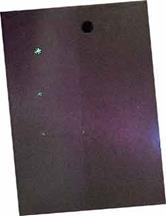
A dry powder developer should be checked daily to ensure that it is fluffy and not caked. It should be similar to fresh powdered sugar and not granulated like powdered soap. It should also be relatively free from specks of fluorescent penetrant material from previous inspection. This check is performed by spreading a sample of the developer out and examining it under UV light. If there are ten or more fluorescent specks in a 10 cm diameter area, the batch should be discarded.
Apply a light coat of the developer by immersing the test component or dusting the surface. After the development time, excessive powder can be removed by gently blowing on the surface with air not exceeding 35 kPa or 5 psi.
Wet Soluble/Suspendable Developer
Wet soluble developer must be completely dissolved in the water and wet suspendable developer must be thoroughly mixed prior to application. The concentration of powder in the carrier solution must be controlled in these developers. The concentration should be checked at least weekly using a hydrometer to make sure it meets the manufacturer’s specification. To check for contamination, the solution should be examined weekly using both white light and UV light. If a scum is present or the solution fluoresces, it should be replaced. Some specifications require that a clean aluminum panel be dipped in the developer, dried, and examined for indications of contamination by fluorescent penetrant materials.
These developers are applied immediately after the final wash. A uniform coating should be applied by spraying, flowing or immersing the component. They should never be applied with a brush. Care should be taken to avoid a heavy accumulation of the developer solution in crevices and recesses. Prolonged contact of the component with the developer solution should be avoided in order to minimize dilution or removal of the penetrant from discontinuities.
Solvent Suspendable (AKA Nonaqueous Wet)
Solvent suspendable developers are typically supplied in an sealed aerosol spray can. Since the developer solution is in a sealed vessel, direct check of the solution is not possible. However, the way that the developer is dispensed must be monitored. The spray developer should produce a fine, even coating on the surface of the part. Make sure the can is well shaken and apply a thin coating to a test article. If the spray produces spatters or an uneven coating, the can should be discarded.
When applying a solvent suspendable developer, it is up to the inspector to control the thickness of the coating. with a visible penetrant system, the developer coating must be thick enough to provide a white contrasting background but not heavy enough to mask indications. When using a fluorescent penetrant system, a very light coating should be used. The developer should be applied under white light and should appear evenly transparent.
Development Time
Parts should be allowed to develop for a minimum of 10 minutes and no more than 2 hours before inspecting.
Quality Control of Lighting
After a component has been properly processed, it is ready for inspection. While automated vision inspection systems are sometimes used, the focus here will be on inspections performed visually by a human inspector, as this is the dominant method. Proper lighting is of great importance when visually inspecting a surface for a penetrant indication. Obviously, the lighting requirements are different for an inspection conducted using a visible dye penetrant than they are for an inspection conducted using a fluorescent dye penetrant. The lighting requirements for each of these techniques, as well as how light measurements are made, are discussed below.
Lighting for Visible Dye Penetrant Inspections
When using a visible penetrant, the intensity of the white light is of principal importance. Inspections can be conducted using natural lighting or artificial lighting. When using natural lighting, it is important to keep in mind that daylight varies from hour to hour, so inspectors must stay constantly aware of the lighting conditions and make adjustments when needed. To improve uniformity in lighting from one inspection to the next, the use of artificial lighting is recommended. Artificial lighting should be white whenever possible and white flood or halogen lamps are most commonly used. The light intensity is required to be 100 foot-candles at the surface being inspected. It is advisable to choose a white light wattage that will provide sufficient light, but avoid excessive reflected light that could distract from the inspection.
Lighting for Fluorescent Penetrant Inspections
When a fluorescent penetrant is being employed, the ultraviolet (UV) illumination and the visible light inside the inspection booth is important. Penetrant dyes are excited by UV light of 365nm wavelength and emit visible light somewhere in the green-yellow range between 520 and 580nm. The source of ultraviolet light is often a mercury arc lamp with a filter. The lamps emit many wavelengths and a filter is used to remove all but the UV and a small amount of visible light between 310 and 410nm. Visible light of wavelengths above 410nm interferes with contrast, and UV emissions below 310nm include some hazardous wavelengths.
Standards and procedures require verification of lens condition and light intensity. Black lights should never be used with a cracked filter as output of white light and harmful black light will be increased. The cleanliness of the filter should also be checked as a coating of solvent carrier, oils, or other foreign materials can reduce the intensity by up to as much as 50%. The filter should be checked visually and cleaned as necessary before warm-up of the light.
Since fluorescent brightness is linear with respect to ultraviolet excitation, a change in the intensity of the light (from age or damage) and a change in the distance of the light source from the surface being inspected will have a direct impact on the inspection. For UV lights used in component evaluations, the normally accepted intensity is 1000 microwatt per square centimeter when measured at 15 inches from the filter face (requirements can vary from 800 to 1200 µW/cm2). The required check should be performed when a new bulb is installed, at startup of the inspection cycle, if a change in intensity is noticed, or every eight hours of continuous use. Regularly checking the intensity of UV lights is very important because bulbs lose intensity over time. In fact, a bulb that is near the end of its operating life will often have an intensity of only 25% of its original output.
Black light intensity will also be affected by voltage variations. A bulb that produces acceptable intensity at 120 volts will produce significantly less at 110 volts. For this reason it is important to provide constant voltage to the light. Also, most UV light must be warmed up prior to use and should be on for at least 15 minutes before beginning an inspection.
When performing a fluorescent penetrant inspection, it is important to keep white light to a minimum as it will significantly reduce the inspectors ability to detect fluorescent indications. Light levels of less than 2 fc are required by most procedures with some procedures requiring less than 0.5 fc at the inspection surface. Procedures require a check and documentation of ambient white light in the inspection area. When checking black light intensity at 15 inches a reading of the white light produced by the black light may be required to verify white light is being removed by the filter.
Light Measurement
Light intensity measurements are made using a radiometer. A radiometer is an instrument that translate light energy into an electrical current. Light striking a silicon photodiode detector causes a charge to build up between internal layers. When an external circuit is
connected to the cell, an electrical current is produced. This current is linear with respect to incident light. Some radiometers have the ability to measure both black and white light, while others require a separate sensor for each measurement. Whichever type is used, the sensing area should be clean and free of any materials that could reduce or obstruct light reaching the sensor. Radiometers are relatively unstable instruments and readings often change considerable over time. Therefore, they should be calibrated at least every six months.
Ultraviolet light measurements should be taken using a fixture to maintain a minimum distance of 15 inches from the filter face to the sensor. The sensor should be centered in the light field to obtain and record the highest reading. UV spot lights are often focused, so intensity readings will vary considerable over a small area. White lights are seldom focused and depending on the wattage, will often produce in excess of the 100 fc at 15 inches. Many specifications do not require the white light intensity check to be conducted at a specific distance.
System Performance Check
System performance checks involve processing a test specimen with known defects to determine if the process will reveal discontinuities of the size required. The specimen must be processed following the same procedure used to process production parts. A system performance check is typically required daily, at the reactivation of a system after maintenance or repairs, or any time the system is suspected of being out of control. As with penetrant inspections in general, results are directly dependent on the skill of the operator and, therefore, each operator should process a panel.
The ideal specimen is a production item that has natural defects of the minimum acceptable size. Some specification delineate the type and size of the defects that must be present in the specimen and detected. Surface finish is will affect washability so the check specimen should have the same surface finish as the production parts being processed. If penetrant systems with different sensitivity levels are being used, there should be a separate specimen for each system.
There are some universal test specimens that can be used if a standard part is not available. The most commonly used test specimen is the TAM or PSM panel. These panel are usually made of stainless steel that has been chrome plated on one half and surfaced finished on the other half to produced the desired roughness. The chrome plated section is impacted from the back side to produce a starburst set of cracks in the chrome. There are five impacted areas to produce range of crack sizes. Each panel has a characteristic “signature” and variances in that signature are indications of process variance. Panel patterns as well as brightness are indicators of process consistency or variance.
Care of system performance check specimens is critical. Specimens should be handled carefully to avoid damage. They should be cleaned thoroughly between uses and storage in a solvent is generally recommended. Before processing a specimen, it should be inspected under UV light to make sure that it is clean and not already producing an indication.
Nature of the Defect
The nature of the defect can have a large affect on sensitivity of a liquid penetrant inspection. Sensitivity is defined as the smallest defect that can be detected with a high degree of reliability. Typically, the crack length at the sample surface is used to define size of the defect. A survey of any probability-of-detection curve for penetrant inspection will quickly lead one to the conclusion that crack length has a definite affect on sensitivity. However, the crack length alone does not determine whether a flaw will be seen or go undetected. The volume of the defect is likely to be the more important feature. The flaw must be of sufficient volume so that enough penetrant will bleed back out to a size that is detectable by the eye or that will satisfy the dimensional thresholds of fluorescence.
Above is an example of fluorescent penetrant inspection probability of detection (POD) curve from the Nondestructive Evaluation (NDE) Capabilities Data Book. Please note that this curve is specific to one set of inspection conditions and should not be interpreted to apply to other inspection situations.
In general, penetrant inspections are more effective at finding
● small round defects than small linear defects. Small round defects are generally easier to detect for several reasons. First, they are typically volumetric defects that can trap significant amounts of penetrant. Second, round defects fill with penetrant faster than linear defects. One research effort found that elliptical flaw with length to width ratio of 100, will take the penetrant nearly 10 times longer to fill than a cylindrical flaw with the same volume.
● deeper flaws than shallow flaws. Deeper flaws will trap more penetrant than shallow flaws, and they are less prone to over washing.
● flaws with a narrow opening at the surface than wide open flaws. Flaws with narrow surface openings are less prone to over washing.
● flaws on smooth surfaces than on rough surfaces. The surface roughness of the part primarily affects the removability of a penetrant. Rough surfaces tend to trap more penetrant in the various tool marks, scratches, and pits that make up the surface. Removing the penetrant from the surface of the part is more difficult and a higher level of background fluorescence or over washing may occur.
● flaws with rough fracture surfaces than smooth fracture surfaces. The surface roughness that the fracture faces is a factor in the speed at which a penetrant enters a defect. In general, the penetrant spreads faster over a surface as the surface roughness increases. It should be noted that a particular penetrant may spread slower than others on a smooth surface but faster than the rest on a rougher surface.
● flaws under tensile or no loading than flaws under compression loading. In a 1987 study at the University College London, the effect of crack closure on detectability was evaluated. Researchers used a four-point bend fixture to place tension and compression loads on specimens that were fabricated to contain fatigue cracks. All cracks were detected with no load and with tensile loads placed on the parts. However, as compressive loads were placed on the parts, the crack length steadily decreased as load increased until a load was reached when the crack was no longer detectable.
Health and Safety Precautions in Liquid Penetrant Inspection
When proper health and safety precautions are followed, liquid penetrant inspection operations can be completed without harm to inspection personnel. However, there are a number of health and safety related issues that must be addressed. Since each inspection operation will have its own unique set of health and safety concerns that must be addressed, only a few of the most common concerns will be discussed here.
Chemical Safety
Whenever chemicals must be handled, certain precautions must be taken as directed by the material safety data sheets (MSDS) for the chemicals. Before working with a chemical of any kind, it is highly recommended that the MSDS be reviewed so that proper chemical safety and hygiene practices can be followed. Some of the penetrant materials are flammable and, therefore, should be used and stored in small quantities. They should only be used in a well ventilated area and ignition sources avoided. Eye protection should always be worn to prevent contact of the chemicals with the eyes. Many of the chemicals used contain detergents and solvents that can dermatitis. Gloves and other protective clothing should be worn to limit contact with the chemicals.
Ultraviolet Light Safety
Ultraviolet (UV) light or “black light” as it is sometimes called, has wavelengths ranging from 180 to 400 nanometers. These wavelengths place UV light in the invisible part of the electromagnetic spectrum between visible light and X-rays. The most familiar source of UV radiation is the the sun and is necessary in small doses for certain chemical processes to occur in the body. However, too much exposure can be harmful to the skin and eyes. Excessive UV light exposure can cause painful sunburn, accelerate wrinkling and increase the risk of skin cancer. UV light can cause eye inflammation, cataracts, and retinal damage.
Because of their close proximity, laboratory devices, like UV lamps, deliver UV light at a much higher intensity than the sun and, therefore, can cause injury much more quickly. The greatest threat with UV light exposure is that the individual is generally unaware that the damage is occurring. There is usually no pain associated with the injury until several hours after the exposure. Skin and eye damage occurs at wavelengths around 320 nm and shorter which is well below the 365 nm wavelength, where penetrants are designed to fluoresce. Therefore, UV lamps sold for use in LPI application are almost always filtered to remove the harmful UV wavelengths. The lamps produce radiation at the harmful wavelengths so it is essential that they be used with the proper filter in place and in good condition.