Introduction
With the great advances in technology in recent years, micro and nanostructures have found many applications. In these structures, micro beams and micro tubes are widely used in nanoscale electromechanical systems such as sensors (Zook et al. [1], Pei et al. [2]), actuators (Senturia [3], Rezazadeh et al. [4]). In investigation of micro and nanostructures, the classical continuum mechanics are not effort of describing of the size‐dependent mechanics. Nonclassical continuum theories such as higher‐order gradient theories and the couple stress theory are capable of explanation of the size‐dependent behaviors, which occur in micro/nanoscale structures.
At the present time, the experimental investigations of the micro/nano materials are still a challenge because of difficulties confronted in the micro/nanoscale. Therefore, mechanical theories and atomistic simulations have been used for nanostructural analysis. The process of the atomistic simulations is very difficult and takes much time. So, continuum theory is the most preferred method for the analysis of the micro and nanostructures. Classical continuum mechanics does not contain the size effect, because of its scale‐free character. The nonlocal continuum theory initiated by Eringen [5] has been widely used to mechanical behavior of micro/nanostructures.
The size effect is very effective in the mechanical behavior of nanostructures at nanometer scale that the classic theory has failed to consider when the size reduces from macro to nano (Toupin [6], Mindlin [7, 8], Fleck and Hutchinson [9], Yang et al. [10], Lam et al. [11]). Therefore, higher‐order theories of modified couple stress theory (MCST) and modified strain gradient are used in the mechanical model of the nano/microstructures (Yang et al. [10], Lam et al. [11]).
The determination of the micro/nanostructural material length scale parameters is very difficult experimentally. So, Yang et al. [10] studied the strain energy of the MCST with one length scale parameter. After this, the MCST and the strain gradient elasticity theories have been widely applied to static and dynamic analysis of beams (Park and Gao [12], Ma et al. [13], Kong et al. [14], Wang et. al. [15], Asghari et al. [16], Wang [17], Simsek [18], Kahrobaiyan et al. [19], Xia et al. [20], Ke et al. [21], Li et al. [22], Akgöz and Civalek [23, 24], Ansari et al. [25], Dos Santos and Reddy [26], Simsek et al. [27], Wang et al. [28], Kocatürk and Akbas [29], Kong [30], Daneshmehr et al. [31], Akgöz and Civalek [32], Ziaee [33], Islam et. al. [34], Miandoab et al. [35], Liu et al. [36], Tang et al. [37], Hosseini and Rahmani [38], Akbas [39, 40]).
The objective of this paper is to investigate static, vibration, and buckling solutions of nanobeams based on modified couple stress theory (MCST). The finite element formulations are derived for static, free vibration, and buckling problems of nanobeams within MCST and the Euler‐Bernoulli beam theory. The effect of the material length scale parameter and geometry parameters on the static, vibration, and buckling responses of the nanobeam are investigated in both the classical beam theory (CBT) and MCST. Also, the difference between the classical beam theory and modified couple stress theory is investigated.
Theory and formulations
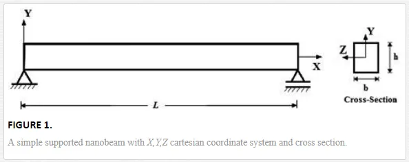
A simple supported nanobeam of length L, width b, and height h, with X,Y,Z cartesian coordinate system is shown in Figure 1.
The modified couple stress theory was proposed by Yang et al. [10]. Based on this theory, the strain energy density for a linear elastic material which is a function of both strain tensor and curvature tensor is introduced for the modified couple stress theory;
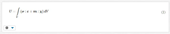
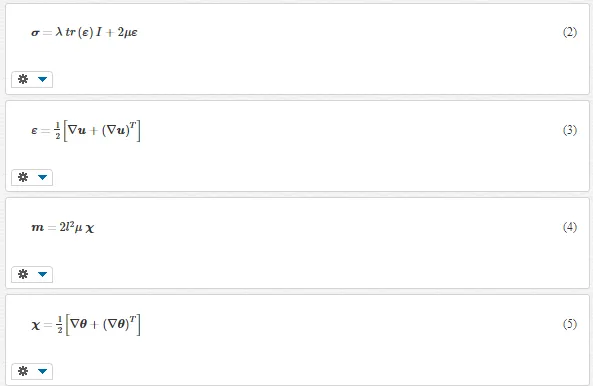
where λ and μ are Lame’s constants, l is a material length scale parameter which is regarded as a material property characterizing the effect of couple stress, u is the displacement vector and θ is the rotation vector, given by
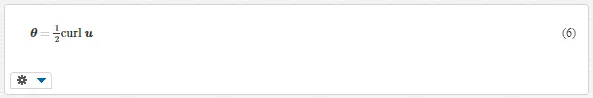
The parameters λ and μ in the constitutive equation are given by
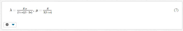
where E is the modulus of elasticity and ν is the Poisson’s ratio. According to the coordinate system (X,Y,Z) shown in Figure 1, based on Euler‐Bernoulli beam theory, the axial and the transverse displacement field are expressed as
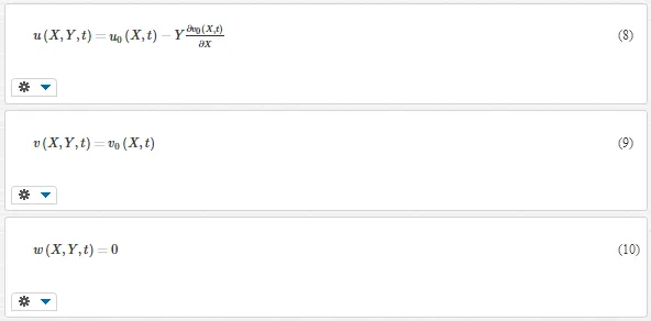
where u, v, w are the x, y, and z components of the displacements, respectively; u0 and v0 are the axial and the transverse displacements in the mid‐plane; and t indicates time. Because the transversal surfaces of the beam are free of stress,
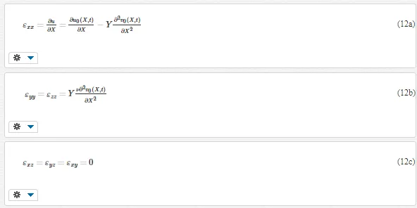
By using Eqs. (3) and (8)–(10), the strain‐displacement relation can be obtained
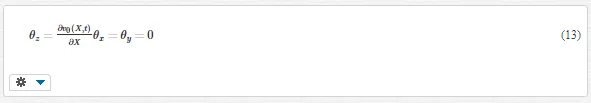
By using Eqs. (6) and (8)–(10),
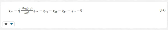
Substituting Eq. (13) into Eq. (5), the curvature tensor χ can be obtained as follows:
According to Hooke’s law, the constitutive equations of the nanobeam are as follows:
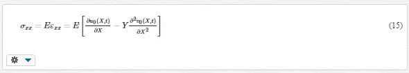
where σxx and εxx are the normal stresses and normal strains in the X direction, respectively. Substituting Eq. (14) into Eq. (4), the couple stress tensor can be obtained as follows:
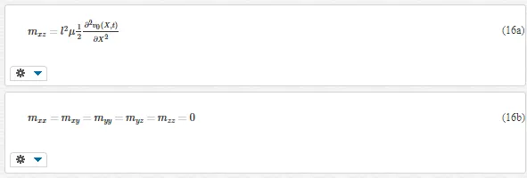
where μ is the shear modulus defined by Eq. (7). The elastic strain energy (Ui) of the nanobeam is expressed as
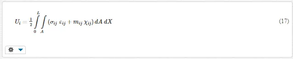
By substituting Eqs. (12) and (14)–(16) into Eq. (17), elastic strain energy (UUi) can be rewritten as follows:
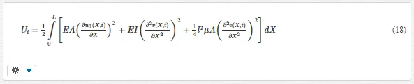
where A is the area of the cross section, and I is the moment of inertia.
The potential energy of the external load can be written as
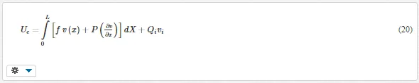
where ff is load function, QiQi is point loads which contains point forces and moments, P is axial compressive load for buckling case. The nodal displacements q for a two‐node beam element contain three degrees of freedom at each node, as shown in Figure 2, namely,
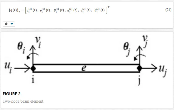
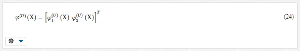
The displacement field of the finite element is expressed in terms of the nodal displacements as follows:
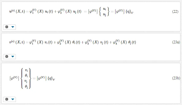
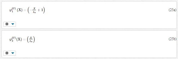
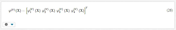
where ui, vi, and θi are the axial displacements, transverse displacements, and slopes at the two end nodes of the beam element, respectively, and φ(U)iφi(U) and φ(V)iφi(V) are the Hermite shape functions for the axial and transverse displacements, respectively. The interpolation functions for the axial displacement are,
Where
The interpolation functions for the transverse displacement are
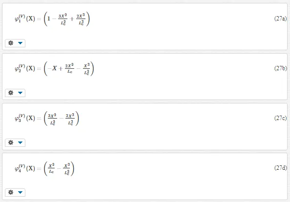
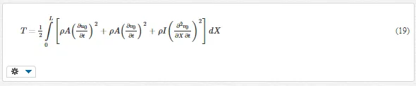
with LeLe indicating the length of the beam element. The Lagrangian functional of the problem is given as follows:
After substituting Eqs. (22) and (23) into Eq. (28) and then using the Lagrange’s equations, one obtains the following equation:
where q˙(e)kq˙k(e) indicates the time derivative of the nodal displacements q.
The Lagrange’s equations can be employed to yield the system of equations of motion for the finite element. By the usual assemblage procedure, the equations of motion can be obtained for the entire structure. For the free vibration problem, the finite element equation is as follows:
For the static problem, the finite element equation is as follows:
For the buckling problem, the finite element equation is as follows:
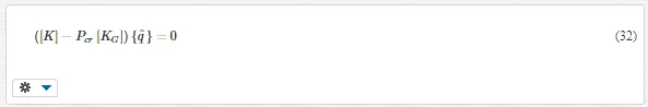
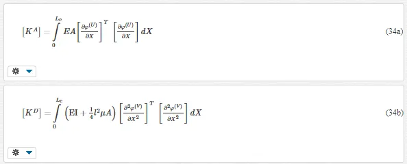
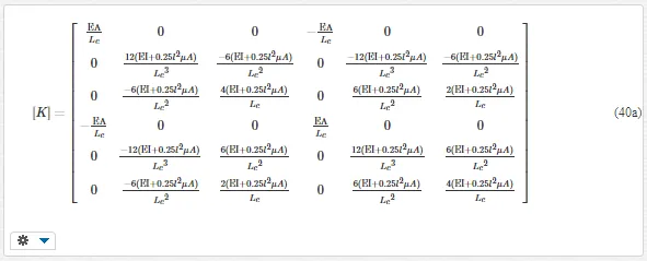
where ω is the natural frequency, {qˆ}{q^} is a vector of displacement amplitudes of the vibration, {F}{F} is the global load vector, [K] is the stiffness matrix, [M] is the mass matrix, and [KG] is the stability matrix. The stiffness matrix [K] can be given as:
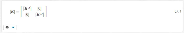
Where
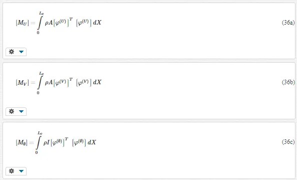
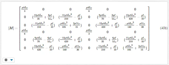
The mass matrix [M] can be expressed as the sum of four submatrices as follows:
Where
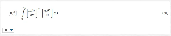
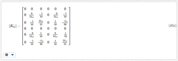
The stability matrix [KG] can be given as:
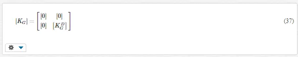
Where
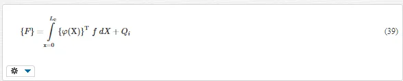
The load vector {F} is expressed as
In the solution of the free vibration and buckling problems, the eigenvalue procedure is performed in Eqs. (30) and (32). When the material length scale parameter (l) is equal to zero, the finite element formulations reduce to classical beam theory.
After integration processing, the finite element matrixes can be expressed as follows:
Numerical results
In the numerical examples, the effects of the material length scale parameter and geometry parameters on the static, vibration, and buckling responses of the nanobeam are presented in both the classical beam theory (CBT) and MCST. Using the conventional assembly procedure for the finite elements, the system stiffness, mass, stability matrices, and the load vector are obtained from the element stiffness, mass, stability matrices, and load vectors. After that, the solution process outlined in the preceding section is used to obtain the solution for the problem of concern. In obtaining the numerical results, graphs and solution of the nonlinear finite element model, MATLAB program is used. The nanobeam is taken to be made of epoxy (E = 1,44 GPa, ν=0.38, l= 17.6 μm, ρ=1600kgm3ν=0.38, l= 17.6 μm, ρ=1600kgm3). In the numerical calculations, the number of finite elements is taken as 100. In the numerical integrations, five‐point Gauss integration rule is used.
In order to establish the accuracy of the present formulation and the computer program developed by the author, the results obtained from the present study are compared with the available results in the literature. For this purpose, the static deflections shapes of a simple supported beam with rectangular cross section, which is subjected to a point load, are calculated for MCST and compared with those of Alashti and Abolghasemi [41] by inserting the material and load properties used in this reference. It is clearly seen that the curves of Figure 3 of the present study are very close to those of Alashti and Abolghasemi [41].
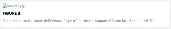
Figure 4a–c shows the effects of the thickness (h) on the static, vibration, and buckling responses of the nanobeam, respectively, in both the CBT and MCST. In these figures, static deflections, fundamental frequencies, and critical buckling loads are calculated and plotted for different values of the h for b = land L = 30 l. In the calculation of Figure 3a, the nanobeam is subjected to a transversal point load (P = 100 μN μN) at the midpoint of the beam in the transverse direction.
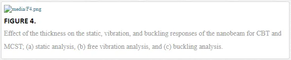
As seen from Figure 4, the difference between the results of the MCST and CBT decreases significantly with the increase in the thickness of the nanobeam. Increase in the thickness of the nanobeam leads to a decline on effects of size effect and difference between the results of MCST and CBT.
In order to see the effect of material length scale parameter (l) on the static, vibration and buckling of the nanobeam, static deflections, fundamental frequencies, and critical buckling loads are displayed with different value of the dimensionless material length scale parameters (l/h) in both the CBT and MCST in Figure 5 for b = 1 μm and L = 30 μm. In this figure, for different values of the dimensionless material length scale parameters (l/h), the material length scale parameter (l) is varied when the thickness of the nanobeam (h) is kept constant as 1 μm.
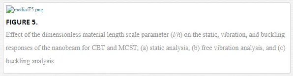
It is seen from Figure 5 that with an increase in the dimensionless material length scale parameter l/hleads to a rise on the difference between the results of the MCST and CBT. Also, the dimensionless material length scale parameter has no effect on the mechanical responses for the classical theory, which is unable to capture the size effect. It is found that the deflections of the nanobeam by the CBT are always larger than those by the MCST. However, fundamental frequencies and critical buckling loads by the MCST are always larger than those by the CBT. It can be seen from figures that the difference between the CBT and MCST is very large when the h and l/h increase. The material parameter and dimension of the nanobeam have a very important role on the mechanical behavior of nanobeams.
Conclusions
Finite element solution of nanobeams is investigated based on modified couple stress theory within the Euler‐Bernoulli beam theory. The finite element formulations are derived for static, free vibration, and buckling problems of nanobeams. The effect of the material length scale parameter and geometry parameters on the static, vibration, and buckling responses of the nanobeam is presented and discussed in the numerical study. Also, the difference between the classical beam theory and modified couple stress theory is investigated.
It is observed from the investigations that the material length scale parameter and dimension of the nanobeam have a big influence on the static, free vibration, and buckling behaviors of nanobeams. With the increase in the thickness of the nanobeam (h) and decrease in the dimensionless material length scale parameter (l/h), the difference between the classical beam theory and modified couple stress theory decrease considerably. It is observed from the results that modified couple stress theory must be used instead of the classical beam theory for small values of nanobeam height and high values of the material length scale parameter.