
CATIA offers two main types of models: Solid and surface. For these, there are two different workbenches you can use:
1. Part design exclusively for solid modeling
2. Generative Shape Design for both surface and solid modeling.
Solid modeling involves different bodies, within which the functions are contained. Note that a body can contain any number of functions, but it is nevertheless essential to work on multiple bodies if one wishes to be able to perform Boolean operations between them.
Surface modeling mainly uses geometrical sets that contain the geometric elements (points, lines, splines, maps …) necessary to create surfaces.
Whether solid or surface modeling, it is important to create as many bodies/sets as you have different materials to be applied to your model.
For 3D printing, it is best to only export files containing volume parts, not surface. In fact, the planar body has no thickness (the thickness is set zero), which can not be translated into anything “physical”. Your 3D model must have a minimum thickness corresponding to the limits of the material used to be correctly interpreted by the 3D printer. We’ll look at the solid bodies in the first step before treating surface bodies in a second step, the latter being less suitable for 3D printing.
Solid modeling: « Part Design » Workbench
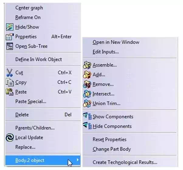
Solid modeling is used for simple geometries for operations such as “positive” (extrusion, revolution, rib …) and “negative” (pocket hole, groove …) It is sensible to create bodies for each operation, so you can easily tweak them against each other through Boolean operations. These boolean operations can be performed at any time of your modeling, although it is common to perform them gradually. They are applicable between all the body parts you have created and are accessible via the ‘Insertion’ tab > ‘Boolean operations’ or simply by right-clicking on the body in question in the tree. For 3D printing, the Boolean operation “add” applied successively to different bodies, will get you a single body ready for printing.
Each function applied by CATIA generates a printable valid model in 3D volume terms. Of course, you still need to respect the constraints of the material you want to use.
You can verify that your model is merged using a section view. This requires that the body belongs to a product. Then you can access the “assembly design” workbench, which contains the “section” tool, located in the toolbar at the bottom of your screen.
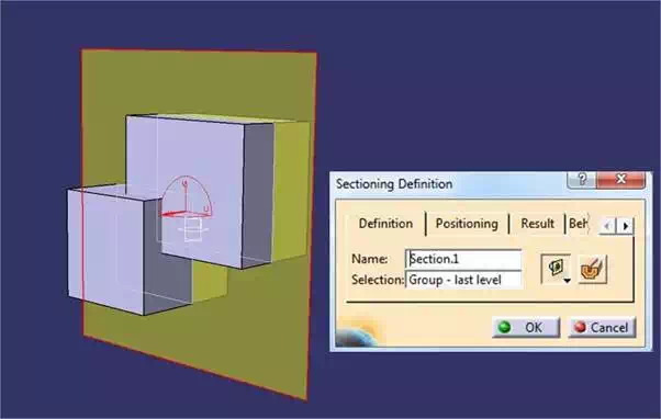
The “section” tool brings up a yellow plan scheme you can move manually or by using the “positioning” tab. You also need to activate the “volumetric cut” icon present in the tool edition. Then, clicking the “results” tab will generate a preview of the cut.
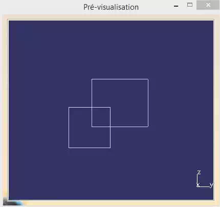
Before the merging the bodies, you can observe two distinct bodies that intersect.
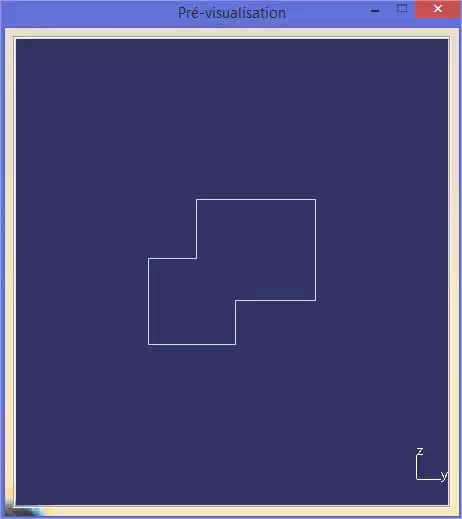
After using “add”, the two bodies are merged as shown in the screenshots below
If your model contains only simple geometric shapes, then it’s highly recommended to use the “design part” workbench. We recommend as much as possible to work in solid bodies for 3D printing. Boolean operations in surface and volume are identical and have the same characteristics.
It may be the case, however, that you need to work on your model surface. In the following section, you will learn how to make a printable surface model.