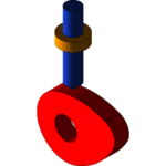
Various types of cam follower are used for different types of applications. You can see an application of the cam follower in another article here about the internal combustion engine. The basic purpose of using the cam follower is converting the rotary motion of the cam to the translating or oscillatory motion of the follower. Before going to the actual design of cam profile, let’s look at the basic terminologies.
Cam Follower Design Terminologies

○ Cam: The cam is the driver. It is normally connected with a prime mover, which rotates it.
○ Follower: With the rotation of the cam, the follower (the shaft with the roller at bottom in the above picture) gets oscillated or translated according to the profile of the cam.
○ Trace Point and Pitch Curve: It is a fixed point of the follower. Locating the trace point is important because the locus of the trace point during the rotation of the follower throughout the periphery of the fixed cam generates the pitch curve. Pitch curve is an imaginary curve.
○ Base Circle: It is a circle with centre as the cam centre and radius equal to the distance between the cam centre and the nearest point of the cam profile.
○ Prime Circle: If you draw a circle with the cam centre as centre and the distance between the cam centre and the trace point as radius, then you will get the prime circle.
○ Pressure Angle: Since in most of cases, the cam profile is not a circle, hence the direction of the movement of the follower differs from the normal to the pitch curve at that point and the angle between the two is called the pressure angle.
Design of the Cam Profile
For the ease of the discussion, let’s take the example of creating the cam profile of a knife edge follower:

We have the following data as input:
Total lift = 80 mm
Base circle diameter = 100 mm
Bottom dwell = 0 to 90 0
Rise = 90 to 1800
Top dwell = 180 to 2700
Fall = 270 to 3600
Types of follower motion = Uniform velocity
○ Draw the 100 mm diameter base circle. In the above picture the smallest of the concentric circle is the base circle.
○ Now draw the outermost of the concentric circle. The radius of the outermost circle is equal to the base circle radius plus the lift of the cam.
○ Since, there is no offset of the follower; hence the cam will be aligned with AB.
○ Now divide the base circle and the outermost circle by 300 sectors. So, there will be total of 12 sectors.
○ Create the follower performance curve as shown by dividing the bottom dwell, top dwell, rise and fall by 12 equidistant parallel sectors. Also, divide the lift height by four equidistant areas.
○ Project the corresponding points of the follower performance curve to the vertical line AB and create the concentric circles.
○ Further join the corresponding intersecting points of the concentric circles and the angular sectors to get the smooth cam profile curve.
Conclusion
The concept discuss in the article remains same for the design of roller cam follower as well, however, you have to consider the roller diameter for such design. AutoCAD can be customized using Autolisp for automating the cam follower design process.


