Graphene is a two-dimensional (2D) analogue of graphite (carbon, or C) material that has exceptional characteristics derived from the bonding characteristics of C bonding sheets. C has four valence electrons, with three of these electrons participating in σ-bonding with its closest neighbors, creating a honeycomb structure. [1] The fourth of these valence electrons occupies an orbital perpendicular to the one-dimensional (1D) sheet creating delocalized π-bonding, as shown in Figure 1, which allows for the creation of a two-dimensional electron gas (2DEG) with high mobility within the sheets. [1, 2]

The delocalization of the π-bonding electrons allows for the graphene sheets to have high mobility, up to 15,000–200,000 cm2/Vs, limited by interactions with the substrate, any contaminant particles, or from itself during bilayer growth. [1, 3–7] This makes cleanliness, grain size, and substrate interference very important issues for growing and using graphene for high mobility and ultrafast applications.
In this review, we are going to focus on the important electrical properties of graphene; however, we should mention some of its other properties for completeness. Due to the 2D nature of a graphene crystal, a single flake will exhibit a large breaking strength of ≈40 N/m due to the absence of slip planes associating the fracture strength of graphene with the strong bonding of c–c in a hex ring. [8] The isolation of electrons from phonons also contributes to the high room temperature thermal conductivity of ≈5,000 W/mK. [9] Along with its high breaking strength graphene is also very pliable with a Young’s modulus ≈1.0 TPa and an elastic strain of up to 20%. [8] These values were partially expected on the basis of previous studies of carbon nanotubes and graphite; although the higher values observed in graphene can be attributed to the crystal defects in samples obtained by micromechanical cleavage.
There are even more intriguing material characteristics of graphene such as shrinkage with increasing Tat all T due to membrane phonons dominating in 2D. [10] Also, graphene exhibits simultaneously high pliability (folds and pleats are commonly observed) and brittleness (it fractures like glass at high strains). [11] Equally unprecedented is the observation that the one-atom-thick film is impermeable to gases, including helium. [12] For electronic applications the structure of graphene creates a semi-metal with a direct Fermi-Dirac band structure, as shown in Figure 1, having charge carriers interacting as Dirac Fermions (with zero-effective mass) that allows for ballistic transport of up to a micron at room temperature. [13– 15] The Fermi-Dirac cone as shown in Figure 1c, however, is modified either by the addition of multiple layers as shown in Figure 2iii, the addition of two layers and doping from contaminant particles (metal or polymer particles lying on the surface) shown in 2iv, or contaminants doping a single layer as shown in Figure 2ii. [16] The contaminant-induced doping would move the Fermi level either up or down, the Dirac cone causing a rounding of the k states resulting in a decrease in the mobility of the current carriers (electron or holes). [16] This, along with the thickness restriction for graphene, creates large resistance and chemical inertness, unless chemically doped and functionalized, making its use for pure conductive applications less attractive. [16, 17]

For applications such as the channel in a field effect transistor, graphene provides an interesting solution since it can be doped electrostatically and has extremely high mobility allowing for quick response. [18] The replacement of Si by graphene for logic gates might be considered due to the high potential switching speed; however, the absence of a band gap means that a relatively large band gap would have to be induced through a variety of doping or other symmetry breaking mechanisms. [18] The absence of a band gap in graphene limits voltage and power gains that is achieved through operation of a device in the saturation regime, along with having a low Ion/Ioff ratio. [16] To overcome this, several doping strategies as shown in Figure 3 have been proposed and tested including: electrostatic doping, chemical doping, and stress or geometry restricted doping by breaking the graphene periodicity (and band properties). [18]

The induction of a band gap has been attempted by multiple groups creating transistors with low on/off ratio and high mobility with a tradeoff between on/off ratio and mobility possible through graphene functionalization techniques.[1] This makes graphene more desirable for applications that require fast response times, but not necessarily big on/off ratios such as RF electronics and IR detectors.
Graphene fabrication
Since graphene’s performance is very susceptible to contamination and structural defects (such as folds, grain boundaries, and pin holes) from processing or the transfer process, a review of graphene growth techniques should be done to determine the benefits and drawbacks of each. [1] Due to the sensitivity of graphene, the growth method must be chosen with the required quality, processing, scale, and device architecture in mind, making exfoliation good for small test structures but inadequate for a repeatable semiconductor targeted process. As shown in Figure 4 there are five major pathways for creating graphene sheets: exfoliation from bulk graphite, unzipping through etching a carbon nanotube, growth from sublimation and reconstruction of carbon from a carbide surface, epitaxial growth from a carbide forming catalyst layer by utilizing condensation during cooling, and the epitaxial growth utilizing a non-carbide forming catalyst layer.

EXFOLIATION
As of 2014, exfoliation methods produced graphene with the lowest number of defects and the highest electron mobility by the pioneers of graphene, Novoselov and Geim, using the adhesive tape method to isolate graphene from graphite.[1, 13, 20] The most common exfoliation method utilizes an adhesive tape to pull graphene films off a graphite crystal, which are subsequently thinned down by further strips of tape and finally rubbed against the desired substrate. This rather crude method creates a random array of single and double layer graphene flakes on the desired substrate that has been a key driver for investigating the many properties of graphene. Since graphene is susceptible to creating folds during this process, it cannot be produced with high accuracy and repeatability, so other mechanical and chemical exfoliation processes have been investigated. To address the difficulties of the scotch tape method, one group tried to exfoliate graphene from highly ordered pyrolytic graphite (HOPG) utilizing a sharp single-crystal diamond wedge penetrating into the graphite source to exfoliate layers. [21] This method has problems with defect initiation through shear stress and the reliable placement of the graphene flakes after exfoliation.
The other main exfoliation method is to utilize liquid-based techniques to create a dispersion of graphene or graphene oxide flakes that are drop-casted or ink-jet-printed, and in the case of graphene oxide subsequently reduced. Liquid exfoliation can be accomplished through the use of solvents or ionic liquids with similar surface tension to graphene, which when sonicated exfoliate the bulk graphite into graphene sheets that can be subsequently centrifuged to create a supernatant and dispersed. [22–25] Probably the oldest known method for producing graphene is through the production of graphite oxide using Hummers’ method, sonicating to create a dispersion and then reduction of the graphene oxide either through the introduction of hydrazine at elevated temperature or through the introduction of a quick burst of energy introduced either through a light burst as shown in Figure 5 (flash or laser) or a temperature spike. [21, 26, 27]

One of the more interesting liquid exfoliation methods utilizes sonicating graphite at the interface of two immiscible liquids, most notably heptane and water, producing macro-scale graphene films. [29] The graphene sheets are adsorbed to the high energy interface between the heptane and the water, where they are kept from restacking. [29] The graphene remains at the interface and the solvents may then be evaporated isolating the graphene flakes. [29] Straightforward mechanical exfoliation methods have been able to produce high-quality graphene flakes that have been very beneficial for the investigation of the amazing characteristics of graphene, while liquid exfoliation (and reduction) methods have been utilized for the production of transparent conducting oxides, conductive inks, and electrodes for Li-ion batteries and super capacitors. Mechanical exfoliation, however, cannot be reliably scaled up to provide the reliable placement and large area high-quality graphene sheets desired for transistor and device applications.
CARBON NANOTUBE UNZIPPING
As shown in Figure 6, graphene can be created by cutting open carbon nanotubes. [7] In one such method, multi-walled carbon nanotubes are cut open in a solution by action of potassium permanganate and sulfuric acid. [30] In another method, graphene nanoribbons were produced by plasma etching of nanotubes partly embedded in a polymer film. [30] This method is useful for producing nanoribbons of graphene that induces a band gap in graphene through geometry breaking, which will be discussed in Section 3. However, the placement of the nanotubes on an integratable chip has been problematic, and thus this method once again is only good for the production of test structures to probe graphene characteristics.

SUBLIMATION AND RECONSTRUCTION FROM CARBIDE
Heating silicon carbide (SiC) or other carbide materials (TaC, NbCm ZrC, HfC, TiC) to high temperatures (>1,100°C) under low pressures (~10-6 torr) boils off the Si (from either the Si face or underlying Si from the C face) and reconstructs the C into a single layer graphene film, although multi-layer graphene has been produced through this approach as well. [19, 32] This process produces epitaxial graphene with dimensions dependent upon the size of the wafer.

The particular face of the SiC used for graphene formation, silicon- or carbon-terminated, highly influences the thickness, mobility, and carrier density of the resulting graphene, with the best results coming from a step edge in SiC that produces “floating” graphene attached to the SiC on the top and the bottom of the step edge as shown in Figure 7. [33] There has also been some work utilizing Ni and Cu bilayers to catalyze the production of graphene from SiC achieving growth at higher pressures and lower temperature. [34] The benefit of using graphene produced from SiC is that SiC is easily integratable with microelectronics processing technologies. The SiC is not desired for most electronics applications, making it desirable to transfer the graphene from its SiC substrate to a more standard substrate such as Si. The sublimation of graphene from SiC also creates a Si2O3 insulating under layer that could assist with the transfer process. Under high temperatures, a large variety of intercalant species can also be placed between the graphene and SiC layer that can potentially help with the exfoliation or the electrical modification/isolation. [19] Under normal conditions, the graphene SiC interface forms a Schottky contact; however, it has been shown that the oxide can be transformed to a nitrogen underlayer through a thermal annealing process in a nitride atmosphere modifying the electronic characteristics between the two. [35]
GROWTH THROUGH CONDENSATION AFTER CARBIDE FORMATION
Graphene growth utilizing a carbonaceous source material (such as methane introduced through a CVD process) differs from material to material with the carbon solubility in the metal and the growth conditions determining the deposition mechanism as shown by the phase diagrams in Figure 8. [7] For carbide producing metallic substrates (such as Ni), graphene growth occurs through a precipitation process during cooling from the carbide. [7] The solubility of C in the metal (Ni for example) is higher at higher temperatures, and thus during the furnace cooling phase carbon diffuses out of its Ni host. [7] The process of forming graphene on Ni has the fundamental limitation that single and few layered graphene is obtained over few to tens of micron regions and not homogeneously over the entire substrate. [7] The lack of control over the number of layers is attributed to the difference in out-diffusion of C from the grains and the grain boundaries of Ni creating non-homogeneous growth conditions.

EPITAXIAL GROWTH OF GRAPHENE ON A NON-CARBIDE FORMING CATALYST
Epitaxy refers to the deposition of a crystalline overlayer on a crystalline substrate, where there is registry between the two. In some cases, epitaxial graphene layers are coupled to surfaces weakly enough (by Van der Waals forces) to retain the 2D electronic band structure of isolated graphene. [31, 32] It is commonly accepted that the production of graphene through the surface absorption of carbon on a non-carbide producing metal (such as Cu or Ir) is an epitaxial process due to the registry between the underlying Cu (or Ir) crystal structure and the graphene layer. Exceptional high-quality single layer graphene growth over large areas have been recently achieved on polycrystalline copper foils.[7] The growth on Cu or Ir is simple and straightforward due to the metallic substrates not having a stable carbide material, thus the decomposition of C is only reliant upon the grain orientation. [36] For example, Cu is an FCC lattice with three dominant grain orientations Cu(100), Cu(110), and Cu(111) along with high index facets which are made up of combinations of low index facets. [36] Cu(100), Cu(110), and Cu (111) have cubic, rectangular, and hexagonal geometries making the Cu(111) grain orientation able to support epitaxial growth. [36] Thus, grain growth on Cu(111) grains tend to be monolayered graphene sheets while Cu(100) and Cu(110) geometries prevent C diffusion causing compact multilayered C islands to form with higher index facets replicating the performance of the lower index grains. [36] Despite the ability for Cu and other metal substrates to grow high-quality graphene flakes for device applications, graphene has to first be transferred onto a semiconducting or insulating substrate when using this growth method. [37] The transference process usually involves spinning on a polymer, etching off the catalyst metal layer, then transferring the graphene onto the desired substrate by placing it on the substrate, and finally etching off the substrate. [37] Both of these processes can produce contaminants on the graphene layer, reducing the mobility by adding scattering centers in the sheet. [1] Groups have been working on ways to reliably reduce these contamination effects; one group has utilized Ti sputtering along with a Ti etch to remove any remaining Cu, while another group has shown that by first spinning on a lift off resist before a normal polymer backing layer produces a much cleaner graphene layer. [38, 39] High-quality graphene has also been shown to be grown between a GaN and Ni interface where the Ni can be peeled off and the graphene layer is left on the GaN substrate. [40]
Graphene doping
Due to the chemical nature of the graphene with its zero band gap, mobility related to the delocalization of the π-bonding orbitals, and lattice periodicity, the doping of graphene can be achieved either through the breaking of lattice periodicity or the electrostatic confinement of the delocalized pz orbitals. [19] There have been several mechanisms proposed and tested that have been effective in shifting the Fermi energy to either p- or n-type regions of the band structure and the creation of p-n junctions at the interface. [19] It should be noted that by breaking the lattice symmetry, the electronic states and band edges are modified as shown in Figure 2, decreasing the mobility. With chemical functionalization, scattering is introduced into the graphene flakes, also decreasing the mobility.

Since graphene is a self-contained sheet with no real interface layer, it should be noted that process integration with oxide dielectrics as shown in Figure 9 can be difficult due to trapped impurities at the interface in terms of creating floating gates for voltage-controlled variable gate transistors. [41] This effect is relevant for device applications of graphene films. It should also be noted that the introduction of trap centers and doping sites through contamination will degrade the continuity of the 2DEG at the trap or dopant site, causing electron and hole pooling to occur. [16, 17, 42]
ELECTROSTATIC DOPING
Electrostatic doping as shown in Figure 10 can be controlled through a variety of methods; some use floating gates with oxide buffer layers and others use direct gate contacts to locally modify the Fermi level allowing for the voltage-controlled operation of the graphene device. [43] Most electrostatic gating is accomplished through a horizontal device architecture to preserve the mobility of graphene for ultrafast devices. With both direct and indirect contact, electrostatic gating can be accomplished by utilizing metals with two different work functions; polymers with different end groups as shown in Figure 11; and finally, layered materials with different opposing band gaps with the higher band gap being the acceptor and the lower being the donor as shown in Figure 12. [19] Metals with dissimilar work functions are normally integrated into a horizontal device with many different combinations to choose from. [44, 45] The amount of gap opening is defined by the difference between the two metal work functions and the induced electric field decreasing down the length of the sheet making the contact placement critical. [44, 45]

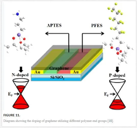
For polymers, the use of different functional groups can electrostatically dope a horizontal graphene sheet with an isolated amine group (isolated nitrogen atom as in nitric acid) n-doping the graphene sheet while fluorine is well known as a good electron acceptor so a polymer containing an isolated fluorine end group p-dopes the polymer as shown in Figure 11. [18] For the polymer electrostatic doping technique, similar atomic dopants are utilized for the chemical doping regime with atoms lower than group V providing n-type doping and elements higher than group V creating p-type dopants (this will create environmental sensitivity within an exposed graphene sheet due to the oxygen and hydroxide adatoms p-doping the graphene). [18, 46]
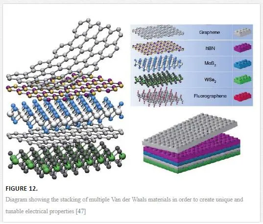
Finally, for electrostatic doping, the utilization of other 2D materials as shown in Figure 12 can be used by vertical device integration with either a homojunction-based device or a heterojunction-based device. For a homojunction-based device, graphene is utilized in a double layer with electrostatic doping coming from a layer above one graphene sheet with a lower band gap (such as tungsten diselenide WSe2) and one below the other graphene sheet with a higher band gap (such as molybdenum disulfide MoS2) creating an electric field between the two 2D materials with different band gaps and electrostatically doping the graphene as shown in Figure 12. [48] Since the electrostatic potential outside a sheet with a band gap will only induce a shift in the Fermi energy for graphene, a heterojunction can be formed between the junction of the 2D materials with a tuning of the upper and lower contacts required. [48] The use of 2D stacked devices is interesting but it should be remembered that many of these layers have not been shown to be readily deposited on top of the other, requiring transfer techniques that can induce defects, transfer contaminants, and have alignment issues between the lattices creating different properties across the lattice due to misalignment as shown in Figure 13. [47, 49]
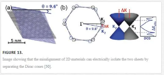
It has been shown that a twist angle between two graphene sheets above 2° electrically isolates the two graphene sheets from one another except at certain twist angles as shown in Figure 13. [49] Most 2D materials have also been shown to have intrinsic doping due to vacancies and edge defects that create more problems for device integration. [49] It should be noted that the mobilities in graphene on boron nitride (BN) substrates have been measured up to 140,000 cm2/Vs, which is very close to completely suspended graphene grown from a SiC step edge, showing the validity of using 2D heterostructures for device integration and isolation. [32, 42]
CHEMICAL DOPING
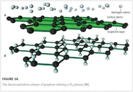
As mentioned briefly in the electrostatic doping section, chemical dopants can be utilized to modify the electrical characteristics of graphene, modifying the Fermi energy to create p- or n-type doping as shown in Figure 14. [19, 46] The chemical doping mechanism of graphene works by having the dopant bond either ionically or covalently to the delocalized pz orbital. [46] The covalent bonding of a dopant with graphene occurs through modification of the delocalized pz orbitals to electrostatically hold an adatom onto the surface, which modifies the band structure by binding the electrons in the pz orbitals, thus creating a required energy (a band gap) for conduction. [46] The chemical dopant can be ionically bonded to a single carbon atom by breaking a c–c bond and attaching to that bonding spot, which breaks the graphene symmetry introducing a scattering defect and a band gap opening. [46, 51] The amount of surface adatoms is reliant upon the dopant and the type of bonding with ionic bonding and larger electronegativity being able to obtain a stronger bond, higher dopant concentration, and higher band gap shifting. [46] However, it should be noted that the higher the doping, the more scattering and the lower the mobility, leading chemical doping to be typically done on vertical devices with a small cross section and thus small diffusion length. [19, 46]
GEOMETRY RESTRICTION
The final way to dope graphene is by breaking the lattice periodicity of graphene as shown in Figure 15. [19, 53] This can be done by reducing the size of a graphene sheet in one direction so that the Fermi levels from the periodic boundary conditions are refined, providing doping through a quantum confinement effect. [53] Quantum confinement occurs when the material dimensions are below the Bohr radius, which for graphene is at 10 nm. [13, 53] This has been shown to be accomplished through the patterning of graphene into ribbons with one dimension restricted to under 10 nm, thus opening a gap of 2.5–3.0 eV in theory and 0.5 eV experimentally. [19, 53] Graphene with a size in either x or y under 10 nm is known as a graphene nanoribbon and it suffers, like many other graphene synthesis techniques, from a lack of a reliable production technique. [53] Traditional semiconductor line definition techniques cannot reliably get a line definition below 20 nm, with large problems creating lines with acceptable line edge roughness. For graphene nanoribbons, the resistance induced through scattering from the line edge roughness is coupled with a lack of graphene conformality, not knowing whether the line definition will create “zig-zag” or “arm-chair” end terminations that provide different conductivity values. [19, 53] The difference between “zig-zag” and “arm-chair” end terminations is shown in Figure 16 and the difference in conductivities between the two create a discrepancy when designing a device utilizing multiple nanoribbons or multiple devices utilizing a graphene nanoribbon. [54]
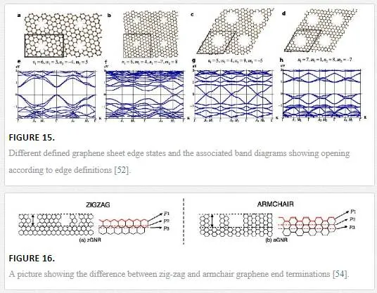
The induced line edge roughness produces many scattering defect reducing the lattice periodicity, obliterating the induced band gap, and decreasing the mobility ultimately limiting the usefulness of graphene nanoribbon formation. [16, 19] Thus, to achieve useful devices from geometry restricted graphene, a reliable method of patterning graphene with low line edge roughness and uniform width must be developed.
Graphene Field Effect Transistors (GFETs) and Radio Frequency (RF) electronics
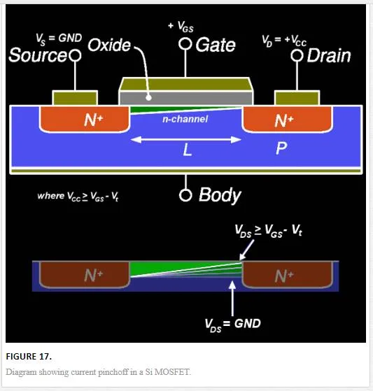
There has been an interest in looking at graphene for nanoelectronics applications due to its high intrinsic mobility allowing for greater switching speed. [18] The main problem with the integration of graphene into three-terminal devices is the lack of a high Ion/Ioff current, which for regular metal oxide semiconductor field effect transistors (MOSFETs) is on the order of 104–107, while for most graphene devices is on the order of 10. [16, 55] This makes graphene-based devices more attractive for the replacement of RF-based devices that are currently dominated by high electron mobility transistors (HEMT) that require a Ion/Ioff ratio of around 30. [16, 55] In addition to this, RF electronics require current saturation to obtain voltage and power gains of around 30, which for graphene means the creation of a band gap through one of the doping mechanisms described above. [16] Saturation current is normally attained through the saturation of charge carrier velocity; however, due to the high mobility of the graphene layer the velocity saturation is unattainable without going to extremely high source drain voltage. [16] Therefore, saturation must be obtained through current pinchoff effects and voltage gain as shown in Figure 17, which can be created in graphene through band gap formation. [16] Even with the formation of a band gap, graphene does not exhibit a saturation current at zero doping due to the Fermi-Dirac cone shape, but the band gap does allow the creation of current pinchoff due to electrical band gap modulation via the source and drain contacts. With this background, we are going to address in the subsequent section several issues that hinder the integration of graphene into FETs that can be utilized for RF applications and review the state-of-the-art technology in terms of GFETs for RF electronics.
SHORT CHANNEL EFFECTS
Graphene normally has a grain size of several to tens of microns with the desire to use a single grain as the channel material to avoid scattering at grain edges (also a factor in current MOSFET structures that is why single crystalline Si is used as a substrate). [16] This creates many of the short channel effects commonly seen in MOSFETS such as drain induced barrier lowering, surface scattering, velocity saturation, impact ionization, and hot-electron effects. [16] Specifically for graphene, drain-induced barrier lowering, surface scattering, and hot electron effects are all in play. Surface scattering is due to the intrinsic susceptibility of graphene to surface contamination and scattering sites, while the hot electron and barrier lowering effects affect graphene due to the pinchoff formation needed to have the large Ion/Ioff ratio required for typical electronics applications and to create large enough voltage and power gains for RF applications.
METALLIC DOPING BY SOURCE DRAIN CONTACTS IN GRAPHENE
Graphene is a self-contained electronic sheet showing no classical band bending interactions when coupled to a metallic contact as shown in Figure 18. This creates an abrupt transition in the vacuum level, creating a barrier that any carrier would have to tunnel through, creating charge buildup at the band edges and large contact resistances. [56]
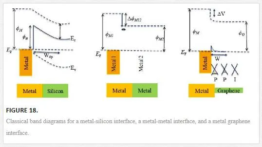
In conjunction to this challenge is the relative inertness of a graphene sheet, making good electrical contacts difficult to realize and mainly occurring at grain edges. [56] This creates a situation where the bulk of the contact sits over the graphene electrostatically doping it, while also trying to realize good adhesion creating a search for a metals with good adhesion to graphene along with the correct Fermi level. [56] To achieve this goal, a double or triple metal stack is commonly used with an oxygen scavenger interfacing the graphene (normally Ti), followed by one or a couple of Fermi level contacts (Au, Pd, Ni). [56] The metallic doping effect, however, can be utilized for some interesting devices such as one using asymmetric contacts to create an internal electric field making an IR detector through the photothermoelectric effect, or using large gap superconducting contacts to confine electrons and holes in a graphene sheet to enhance bolometric response. [45, 57]
DIELECTRIC DEPOSITION AND TRAP STATES
As stated in Section 1 and Section 3, graphene is a self-contained layer without any dangling bonds, thus adhesion and interfaces with graphene are a challenge. Multiple groups have been experimenting with different types of oxides with either an aluminum deposition and oxidation or a nitrogen dioxide surface pretreatment prior to a hafnium oxide, silicon dioxide, or aluminum oxide deposition. [58] The dielectric which seems to work the best (but has not yet been implemented in a complementary metal oxide semiconductor (CMOS) fabrication process) is another 2D self-contained dielectric BN with which graphene has shown mobilities of 140,000 cm2/Vs, which is very close to completely suspended graphene grown from a SiC step edge, demonstrating low interaction and good isolation between the two substrates. [42]
FET DESIGN AND GATE COUPLING
To overcome some of the short channel issues and problems with graphene integration into common process flows, a wafer bonding type of integration has been suggested as shown in Figure 19. [59] This allows for the separation of the drain and gate contacts, which reduces coupling and alleviates some of the issues with drain induced barrier lowering. [60]
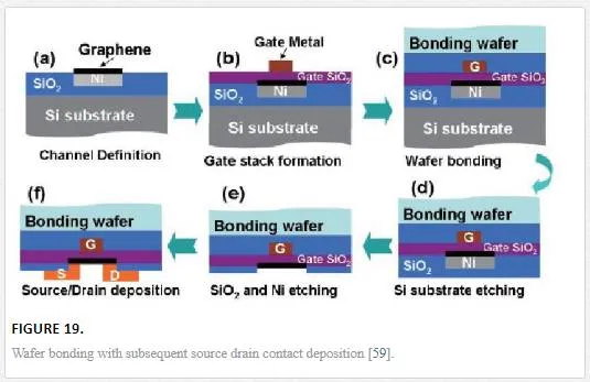
Gate coupling is a significant issue with graphene FETs due to the large gate voltages needed to create sufficient barriers for high Ion/Ioff ratios, the metallic characteristic of the graphene layer, the thin gate oxide needed to ensure good gate control and reduced gate potential for smaller electrical field propagation, and finally the dielectric breakdown strength. [60] All of these needs show that a thin high-k gate with opposing gate and source drain contact geometry is desired as shown in Figure 19.
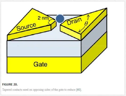
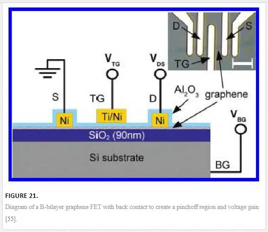
Graphene devices have a very thin cross section where the active electric field can affect one another. It has been shown that by using tapered contacts as shown in Figure 20, the amount of source drain coupling is reduced due to electric field reduction. [60] This is especially effective if utilizing a back gate design as shown later in Figure 21, or a large gate that could overlap the source and drain contacts on the opposing side of the devices channel. [55, 60]
GRAPHENE FET AND RF ELECTRONIC PERFORMANCE
In order to create a device that allows for the opening of a band gap required for current saturation and appropriate voltage and current gains, several device geometries have been proposed. [16, 55] The main mechanisms for increasing graphene performance in FETs is to increase gate coupling with graphene layer and to optimize the graphene dielectric interface to reduce scattering and make the conduction and valence states continuous. [16]
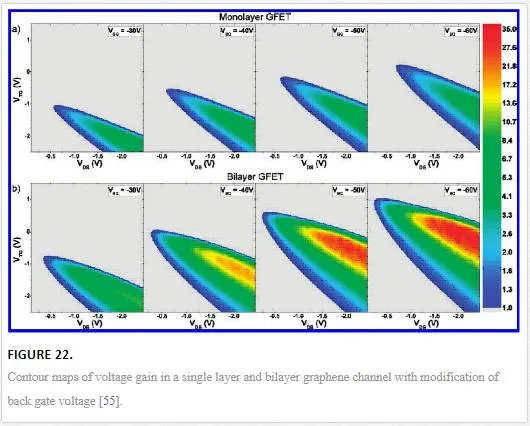
One possible device geometry shown in Figure 21 utilizes a bilayer graphene channel with a large backgate voltage to induce an electric field of 1.7 V/nm that opens a band gap in bilayer graphene of 80 meV with the Mexican hat shape shown in Figure 2iv. [16, 55] The band gap creates a saturation current due to pinchoff at the drain contact resulting in a voltage gain of 35, which is relevant for RF electronics.
This mechanism works much better for bilayer graphene than monolayer graphene as bilayer graphene more easily forms a pinchoff region. To demonstrate this, the amount of voltage gain in such a graphene FET is graphed as contour plots with voltage gain axis on the right hand side of the graph as shown in Figure 22. [55]
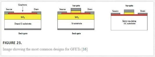
Current designs for graphene FETs are shown in Figure 23, with the back gated design commonly used to overcome any doping in the graphene channel due to substrate, atmospheric, or dielectric effects. [16] The back gate and top gate design are the most common since these allow for the shifting of the Dirac point to zero through an induced electric field and proper gate modulation. [16]
Utilizing a three-terminal top gate design of CVD graphene grown on a SiC substrate, one group was able to achieve a 350 GHz cutoff frequency, utilizing a channel length of 40 nm as shown in Figure 24. [61]
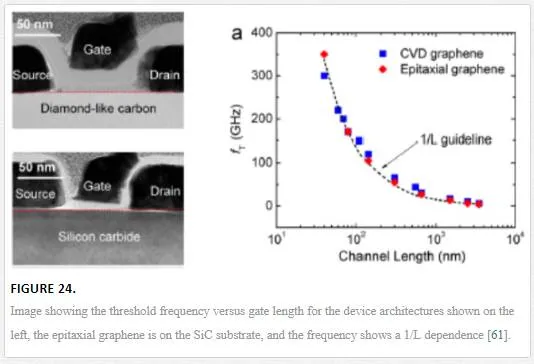
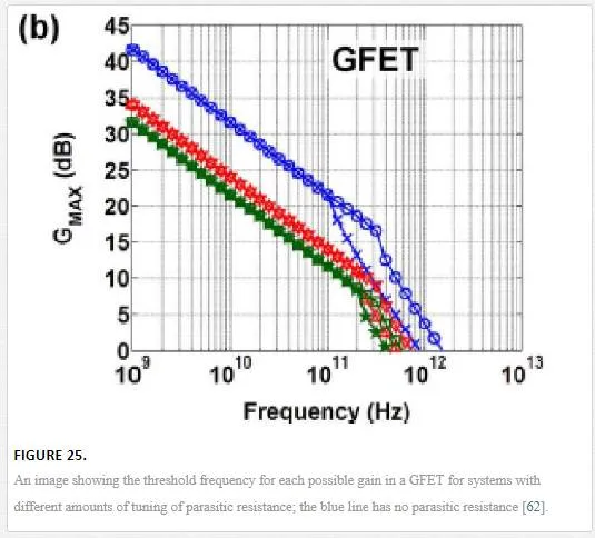
This group showed that the threshold frequency has a 1/L dependence, where L is the channel length of the graphene FET. This has been modeled and pushed to the limit with an understanding that graphene might be able to break the 1THz limit that InGaAs and SiGe HEMTs can’t break. [62] One group theoretically tuned all of the parasitic capacitances that would limit the graphene channel mobility; this includes removing Schottky interactions at the source and drain contacts, removal of any trapped states in the oxide, ignoring any electron/hole pooling effects, and having the gate voltage perfectly coupled to channel potential, allowing for a GFET that operates at 1.5 THz. [62] This GFET is optimized to have zero gain due to the current saturation in the 50 nm channel. [62] By allowing for current saturation in the GFET, a voltage gain can be engineered in the graphene channel; however, this would deteriorate the operating frequency of the GFET as shown in Figure 25. [62]
Graphene use in Electro-Optical (EO) devices
One of the interesting applications for graphene is its use in EO devices and lasers. Graphene can absorb wavelengths from the visible to the mid-IR with wavelength modulation enabled through electrostatic gating. [63–67] The electrostatic gating interacts with light either by modulating the band gap width up to a certain wavelength working as an absorption modulating element, or it modifies the graphene surface plasmon modes that interact with light. [63–67] The last example is how graphene was utilized for mode locking a laser. [63–67] The problem with utilizing graphene for pure optical devices is due to its inherent thinness only absorbing 2.3% of the incident light per monolayer. [63–67] This makes it more desirable to integrate graphene with other electro-optical components such as photonic cavities or plasmonic waveguides with an example shown in Figure 26. [63–67]
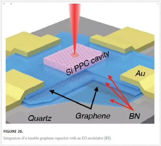
The EO modulator pictured in Figure 26 was created through the coupling of Si plasmonic nanocavities to a tunable graphene capacitor made from stacked layers of graphene and BN dielectric film. [63] The top and bottom graphene layers are electrostatically doped differently from one another with varying voltages for optical modulation of absorbed light. [63] The modulator worked up to 1.2 GHz frequency, which was limited by the RC time constant of the capacitor. [63] Although on its own graphene is not practical for use as a waveguide or modulator, it can be combined with already active materials to increase the performance of such devices.
Graphene Infrared (IR) detectors
IR detectors can be separated into two separate categories: thermal-based IR detection and photon-based detection. [68] In thermal-based detectors, the incident IR radiation is absorbed, raising the temperature of the material. [68] The raised temperature affects some temperature-dependent property of the material; for pyrometers this is a change in electrical polarization, while for bolometers, this is a change in materials resistance. [68] Another more recent study utilized the photothermoelectric effect in graphene to create a net electric field due to electron diffusion into dissimilar metal contacts. [45] Photon-based detectors utilize band gap-based detection with the arriving photon being absorbed and utilized to promote electron hole pairs to create a photocurrent. [68] The photon-based detectors can be tuned to certain wavelengths by creating a quantum well structure. [68] Photon-based IR absorbers are characterized by having fast absorption response, but usually require cooling due to thermal effects, while thermal-based IR detectors have high responsivity over a large wavelength and can be utilized at room temperature but normally have slow absorption response. [68] This is where utilizing a graphene-based sensing element is attractive due to the high mobility with little temperature sensitivity making it ideal for IR detectors. [2]
Several groups have attempted to integrate graphene into IR detectors. The groups have tried both photon- and the thermal-based absorption methods. [45, 69–74] For photon-based absorption methods, the main focus has been the opening of a band gap through geometric modification. [45, 69] One group utilized bilayer graphene to open a small band gap that is sensitive to thermalization requiring cooling to 5 K for operation. [69]
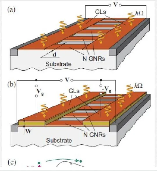
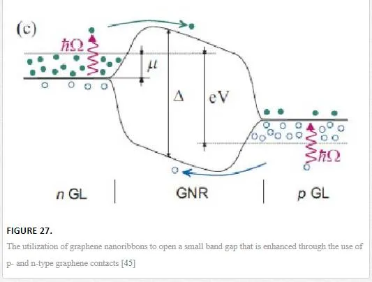
Another group utilized an array of aligned graphene nanoribbons as shown in Figure 27 to open up a small band gap that has significant difficulties in fabrication and noise properties from the nanoribbon edges. [45] Groups that have tried thermal-based IR detectors seem to have created more novelty, with one group utilizing multiple vertically aligned graphene flakes, while another group utilized a resonant structure of two graphene sheets separated by a dielectric to tune the photon wavelength of absorption as shown in Figure 28. Finally, another group utilized the photothermoelectric effect as shown in Figure 29 to induce an electric current in graphene due to electric gating or dissimilar metal contacts. [45, 70, 71] The bolometer utilizing vertically aligned graphene sheets used distance-based tunneling between sheets for the bolometric effect, which is sensitive to contamination between sheets and alignment of the graphene flakes making reproduction difficult. [71
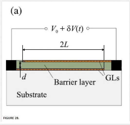
The resonance-based IR detector shown in Figure 28 utilizes the phonon resonance of two separate graphene sheets separated by a dielectric allowing for the tuning of wavelength detection based upon separation distance, but the fabrication is difficult requiring pristine graphene and no trapped states in the oxide that would both modify the resonant frequency and could possibly contaminate the detector out of detection range. [70]
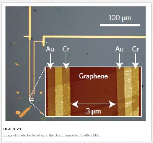
The photothermoelectric effect detector shown in Figure 29 is relatively straight forward with contamination only affecting the speed of the detector and the noise only susceptible to trap states of the insulating oxide that the graphene is transferred onto. [45]
Conclusion
We have shown graphene to have many amazing properties due to its unique bonding and subsequently band gap characteristics, having electronic carriers act as “massless” Dirac-Fermions. The material characteristics of graphene are anisotropic, having phenomenal characteristic within a single sheet and diminished material characteristics between sheet with increasing sheet number and grain boundaries. This restricts the applications of graphene to technology that is consistent with miniaturization such as microelectronics. Therefore the integration of graphene into several electronic device applications was reviewed.
Graphene has the highest mobilities values measured in a material at room temperature making integration into fast response time devices such as a HEMT for RF applications. It has been shown that although the integration of graphene is challenging due to mobility degradation due to surface contamination in the graphene and trapped states in the oxide dielectric, a graphene RF detector with an overall response frequency of 300 Ghz was achieved utilizing a three-terminal design on a SiC substrate with a channel length of 40 nm.
Graphene use in optical devices is limited due to the absorption of 2.3% of incident light per layer making graphene’s use for optical devices a tradeoff between getting enough layer for good optical absorption and modulation versus restricting number of layers for fast carrier propagation. On its own, graphene is not practical for use as a waveguide or modulator but when it is combined with already active materials, it increases the performance of such devices thus an EO modulator utilizing a stacked graphene-BN capacitor along with a Si microcavity array displays the ability to modulate light at a rate of 1.2 GHz.
Graphene for IR detectors has shown some promising results utilizing graphene in thermal-based detection regimes since photon-based absorption regimes all require inducing a band gap, adding complexity and reliability issues. The unique thermal-based properties of graphene either in a traditional bolometric type of device or one based upon current produced from the photoelectric effect allowed for the creation of a graphene IR detector with sensitivity to a 2.5 THz (119µm) laser.
