Studying the interaction between fluids and structures is becoming increasingly important in today’s design world. The reasons for this are simple. How can you fully understand what’s happening in a fluid when its boundaries are subject to change? How reliable is your structural design when you don’t really know what that fluid providing the load is doing? From injection nozzles to wind turbines, fluid- structure interaction plays an important role in the design process.
Coupled Fluid-Structure Interaction (FSI) analyses are necessary, for example, when the fluid pressure creates a significant structural deformation at the fluid boundaries, which, in turn, alters the fluid pressure. Computational Fluid Dynamics models (CFD) and a structural Finite Element models (FE) are commonly used in FSI. Analytical codes must link the CFD and FE models, with the end result being the Reese’s Peanut Butter Cup of the analytical world.
Getting two different analytical models to interact is only one of the many challenges of the FSI world. The reason the two models differ is because the minds that created them think and act differently. FSI modeling is akin to the Star Trek Next Generation episode where the Enterprise encounters a new race of equal strength but with a completely alien method of expression. When both captains are marooned on a hostile planet and forced to work together to survive, they find a way to communicate to achieve a common goal.
 |
Well, fighting a murderous energy creature is probably more challenging than getting CFD and FE engineers to communicate, but there are many parallels. CFD and FE people might as well be from separate planets due to the number of differences between them. One uses elements, the other uses cells. One models a part, the other models the space in or around it. One talks about shape functions the other about turbulence models. Even a Star Trek universal translator couldn’t help here.
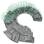
The key to communicating begins with the thing they have in common: the fluid-structure boundary. Analytical codes that take on FSI have to know where the interface surfaces are in both the structure and the fluid models. The code has to be able to share the fluid properties (pressure for instance) with the structure and then return a movement of the fluid boundary (structural deformation) to the CFD model.
This requires mapping results from one model to the other. Generally, the CFD and FE models have different element formulations. The mesh sizing on the interface surfaces can vary widely because the meshing criteria differ for the two applications. For instance, the FE mesh distribution is driven by the need for an accurate definition of stiffness as well as derived quantities like strain and stress. The CFD cell distribution is often driven by boundary wall phenomena like transitional flow from laminar to turbulent. The FSI software must be able to accurately distribute the results from the elements of one model onto the mesh of the other.
So, we now have two models, a shared designation of the boundary surfaces where they interact and an ability to map results across dissimilar sizes and shapes of our elements. Sounds like we are there, right? Well not so fast chum; let’s keep in mind that these systems are typically nonlinear in their response which means we will have to contend with a term that can strike fear into the heart of even the most experienced engineering analyst: Convergence!
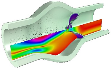
Individually, the CFD and FEA codes have a pretty good handle on how to determine if a nonlinear solution has converged for a given set of boundary conditions. Linking the two systems together makes the solution more sensitive because those boundary conditions are now solved for iteratively. As an example, consider flow through a flexible hose. Initially the pressure distribution is solved in the CFD model based on a fixed boundary and the input and output flow definition. The resulting pressure distribution is applied to the wall of the hose in the FE model and the hose expands. The expanded boundary is returned to the CFD model where the pressure is recalculated based in the adjusted volume of the flow region. This process needs to continue until the change between steps becomes acceptably small for each time increment.
Pictorially, the convergence process can look something like this:
 |
So, for a given time increment we need to achieve a converged solution for both the FEA and CFD solutions and then loop through the process until the FSI solution is converged. When you consider that some FSI problems can require very small time steps…..well, you can see where this is going.
Since we generally prefer to have our FSI solutions complete within our lifetime, there is always a balance between the amount of detail we need in the solution and the computational time required to solve it.
However, this does not lessen the value of the FSI approach. The things that can be learned from an earnest and detailed evaluation of fluids and structures together has the potential to save both time and cost in the design process. Designs can be made more efficient, costly physical testing can be reduced and a lot insight into the products you design can be gained.