Whatever we design life will verify it at the end… but I would rather know if my design has a fighting chance before any major collapse occurs!
This is why FEA results verification is a very important thing.Here are the 5 steps of FEA results verification
1. Check the shape of deformations
I think that shape of the deformation is more important than its value! Checking how the shape of the deformation looks like gives you a chance to think whether the model works as intended! This is not a code-check or a demand your Customer will have. This step is only for you, as it allows you to see if everything went well.
Note that you may need to increase the scale of deformations dramatically to see the model behavior. Again: this is not about the value of the deformation, but about the shape of it!

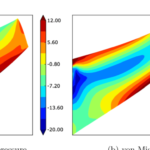
2. Check deformation values
Checking deformation values may be a bit tricky. This is because the software usually “auto-scales” deformations based on the model size. This means that what you see on a screen is not the “actual” deformed shape, but rather shape with scale factor selected by the software automatically (to “enhance” user experience).
I admit this is usually a nice feature, but it can be greatly misleading. Be sure to set the deformation scale to 1.0 and vied the deformed model there as well.
Bear in mind that too big deformations aren’t the only issue here. If you know that the model should deform, but it didn’t something is wrong just as well!
3. Check reaction forces
There are few things here that you should be interested in:
- Firstly, check if all simplifications in supports you have made still hold
If you modeled a flower pot standing on the ground, you may have omitted contact definition and model a vertical support on the entire bottom surface of the book. This is great… unless you get a tensile force in that support! Such load could not appear there (unless the pot is glued to the ground of course).
With this in mind, if you would get a tensile reaction force in that support you know that the assumption you have made (to ignore contact) doesn’t hold!
This is a very common mistake, that can lead to big mistakes in boundary conditions – more on this in one of the lessons of my free FEA essentials course.
- Check the force – reaction force balance
Unless you do serious dynamic analysis active forces should be in equilibrium with reaction forces. Since you usually know how much load you have applied (a good thing to know!) just check the total reaction force in any given direction, and see if the value of total load in that direction is a match. It should be! If not, something went wrong…
- Check the “soft springs” (aka the “air hooks”)
From time to time, you will analyze a problems that are “a bit” unstable. You will most likely stabilize it with a very soft spring (sometimes called an “air hook”). This is a completely fake support but it helps with numerical calculation of the problem.
When you finish the analysis it is a very good idea to check reaction forces in those soft springs… Since there is no real support there, the reaction force should be minimal!
If that is not the case… you need to rethink softness of the spring or a place where you have added it.
If you have changed the placement of soft springs several times, and you still get huge forces in air hooks, maybe your model is so unstable that it simply won’t work?
- Consider boundary conditions you have chosen
If you have doubts about what boundary conditions to use, use both sets and compare outcomes. This way you will see if the assumption you are uncertain about will play any significant role in design.
Also, thanks to the fact that you can take a look at a deformed model in both cases, you may be able to decide which solution is more realistic.
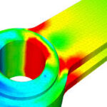
4. Take a look at stresses
I usually do this while checking if stresses are acceptable. But the goal here is not to assess if the part you have calculated is good or need strengthening. We are checking if the outcomes we get make any sense at all!
By default, your software will most likely show you the average stress. This may not be the perfect approach. Just find the place where averaging is being used, and turn it off. You will be surprised how much the outcomes may change!

If the differences in stresses are big for adjacent elements, you should consider refining mesh in that region!
Usually, there are several options on how outcomes are displayed in your software. Learn about them and use them wisely!
5. Do the hand calculations!
This always gets me at least few weird looks but I feel that verification of FEA outcomes with simplified calculations is a freaking super-power!