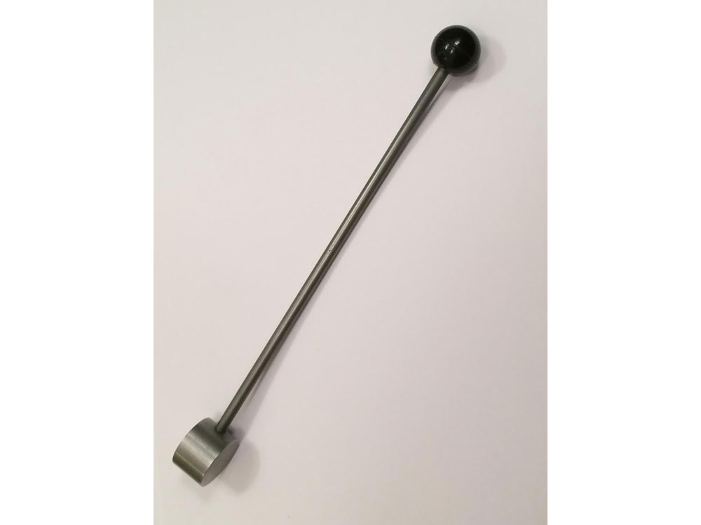
Slip gauges

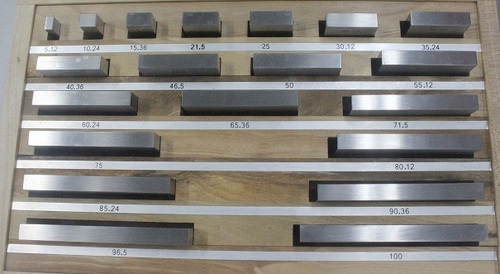
These  gauges  are  otherwise  called  as  Gauge  blocks  or  Block  gauges  and  are  universally accepted as end standards of length in industry.  Slip gauges are rectangular blocks of high grade steel (or tungsten carbide) with less co-efficient of thermal expansion.  These blocks are highly hardened (more than 800 HV) through out to ensure maximum resistance to wear and are then stabilised  by  heating  and  cooling  successively  in  stages  so  that  the  hardening  stresses  are removed.  After hardening, they are subjected to lapping to a high degree of finish, flatness and accuracy.   The cross sections of these gauges are 9 x 30 mm for sizes up to 10 mm and 9 x 35 mm for larger sizes.  The dimension (height) is marked on one of the measuring faces of gauge blocks. Wringing of Slip gauges: The slip gauges are wrung together by hand through a combined sliding and twisting motion. The air gap  between the gauge faces is expelled out  and the adhesion is caused partly by molecular attraction and partly by atmospheric pressure. The gap between the two wrung slip gauges is only of the order of 0.00635  m which is negligible. Selection of Slip gauges for required dimension: Always start with the last decimal place and deduct this from the required dimension.  Select the next smallest figure in the same way, find the remainder and continue this until the required dimension is completed.   Minimum number of slip gauges should be selected to build up the given dimension.

Read More

Comparator

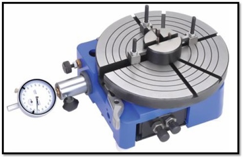
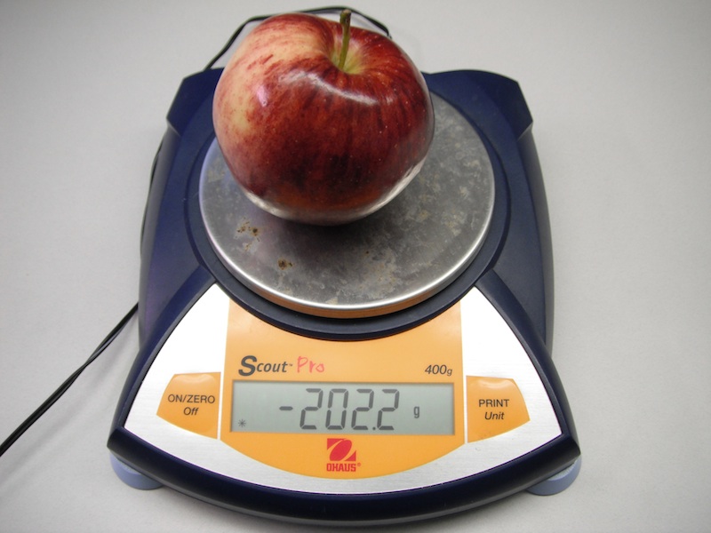
It is a precision instrument employed to compare the dimension of a given component with a working standard (generally slip gauges). It does not measure the actual dimension but indicates how much it differs from the basic dimension (working standard). Uses of Comparator:   For calibrating the working gauges   Used as working gauges   Used as final inspection gauges Essential characteristics of a good Comparator:   Robust design and construction   Linear characteristics of scale   High magnification   Quick in results   Versatility   Minimum wear of contact point   Free from back lash   Quick insertion of work piece   Provision for compensation from temperature effects   Provision for means to prevent damage during use. Classification of comparators: 1)  Mechanical comparator a)        Dial indicator b)        Johansson „Mikrokator‟ comparator c)        Sigma comparator d)        Reed type mechanical comparator 2)  Optical comparator: a)        Zeiss Ultra optimeter b)        Zeiss optotest comparator 3)  Mechanical – Optical comparator 4)  Electrical comparator 5)  Fluid displacement comparator 6)  Pneumatic comparator a)        Back pressure comparator b)        Flow – velocity Pneumatic comparator In addition, the comparators used in standards room for calibration of gauges are: 7)  Brookes Level comparator 8)  Eden-Rolt „Millionth‟ Comparator

Read More

Based on control

1)  Controllable errors:  The sources of error are known and it is possible to have a control on these sources.   These can be calibration errors, environmental errors and errors due to non- similarity of condition while calibrating and measuring. Calibration errors:  These are caused due to variation in the calibrated scale from its normal value.  The actual…

Read More

Instrumental error

1)  Error of a physical measure:    It is the difference between the nominal value and the conventional true value reproduced by the physical measure. 2)  Error of a measuring mechanism:   It is the difference between the value indicated by the measuring mechanism and the conventional true value of the measured quantity. 3)  Zero error: It is the indication…

Read More