Suresh Kumar is a passionate mechanical engineer with deep expertise in design, thermodynamics, manufacturing, and automation. With years of experience in the industry, they simplify complex engineering principles into practical insights for students, professionals, and enthusiasts. This blog serves as a hub for exploring cutting-edge innovations, fundamental concepts, and real-world applications in mechanical engineering.
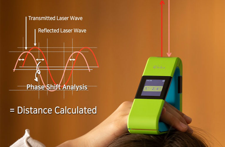
Introduction: “Light Amplification by Stimulated Emission of Radiation”. Laser metrology Laser telemetric system Laser and led based distance measuring instruments Scanning laser gauge Photodiode array imaging Diffraction pattern technique Laser triangulation sensors Two frequency laser interferometer Gauge wide diameter from the diffraction pattern formed in a laser. Principle of laser: The principle involved in laser is when the photon emitted during stimulated emission has the same energy, phase and frequency as the incident photon.…
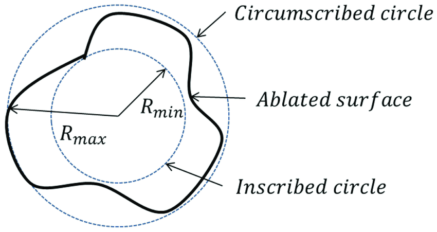
Roundness or circularity: Is the radial uniformity of work surface measured from the centre line of the work piece. Methods of measuring roundness: V- block and dial indicator method Roundness measuring machine
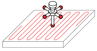
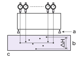
Flatness: A surface is said to be flat within a given range of measurement. Flatness testing: r anauto If the test surface is large, then it is tested for flatness using a sprit level o collimator. Procedure to determine flatness: A surface can be considered to be a collection of a large number of lines. Flatness testing by…
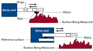
Introduction: Contain degree of surface finish is required for the proper functioning of the working surface. Types of surface finish: Nominal surface Rough surface Wavy surface Elements of surface texture: Surface roughness Profile…